444 01-6203-01R3, CG Drives & Automation
12.14. Configuration of analog inputs
12.14.1. Analog input 1
Settings for analog input 1.
Details
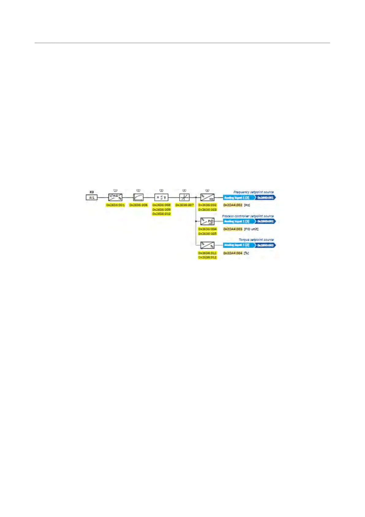
The analog input 1 can be used as setpoint source.
Selection of setpoint source
93
For the process controller, the analog input can be used for the feedback of the variable
(actual value) or speed feedforward control. Basic process controller settings
233
The following settings are possible for the analog input:
• Definition of the input range
①
• Filter time for low-pass filters
②
• Monitoring of the input signal
③
• Dead band for eliminating the smallest signal levels
④
• Definition of the setting range
⑤
Diagnostic parameters:
• The frequency value is displayed in 0x2DA4:002 (P110.02).
• The process controller value is displayed in 0x2DA4:003 (P110.03).
• The torque value is displayed in 0x2DA4:004 (P110.04).
Definition of the input range
The analog input can be configured as voltage or current input. Internally, the signal is
always converted to a value in percent.
Definition of the setting range
The setting range results from the set min and max value for the respective mode.
Configuration examples
Detailed configuration examples can be found in the following subchapters:
Example 1: Input range 0 ... 10 V ≡ setting range 0 ... 50 Hz
425
Example 2: Input range 0 ... 10 V ≡ setting range -40 ... +40 Hz
425
Example 3: Error detection
426