4.3.4. Function assignment of the inputs and outputs
The inverter control can be adapted individually to the respective application. This is
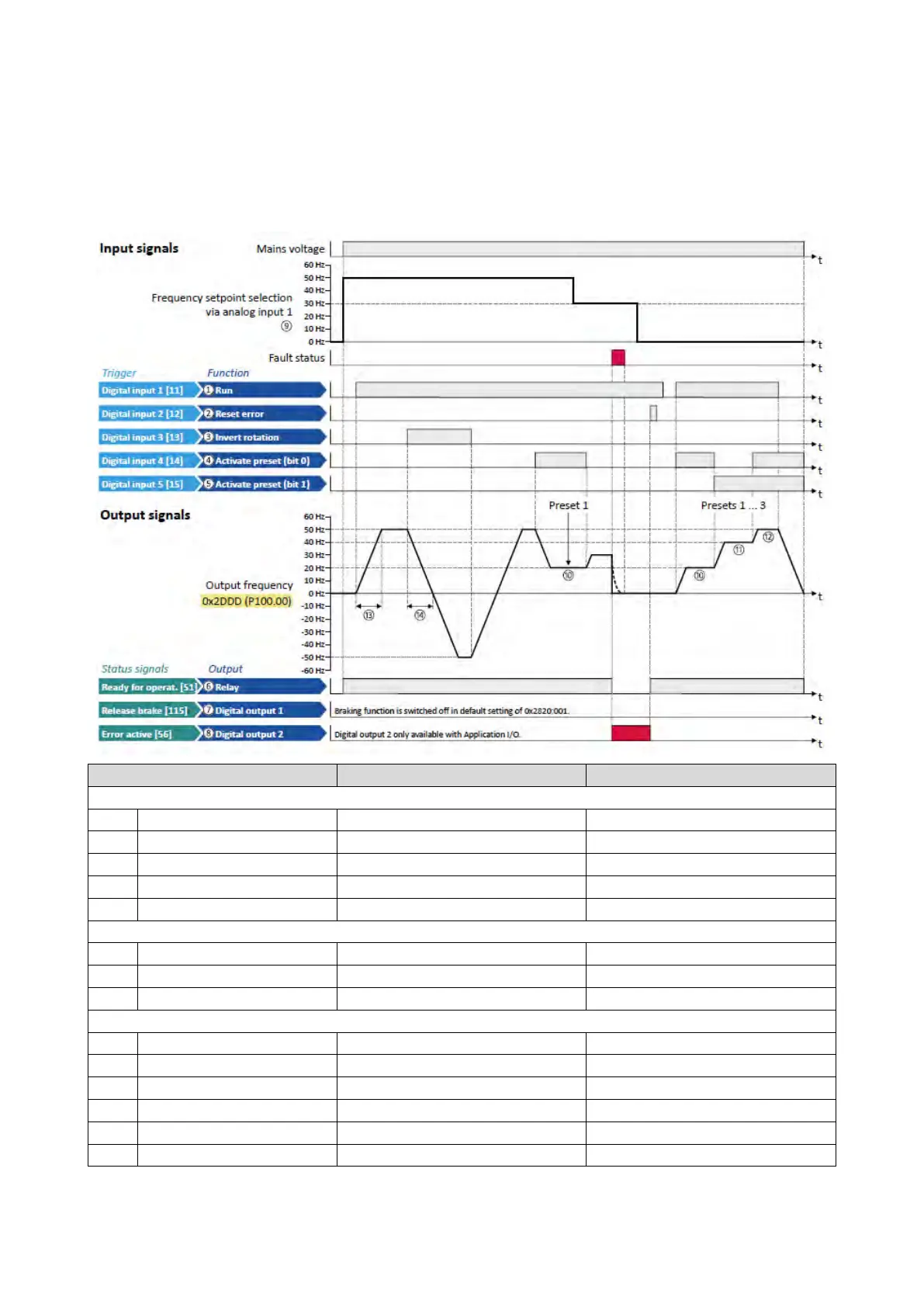
basically effected by assigning digital control sources ("triggers") to functions of the
inverter.
By default, the inverter can be controlled via the I/O terminals as follows:
①
0x2631:002 (P400.02) Run Digital input 1 [11]
Configuration of digital outputs
Release holding brake [115]
Digital output 2 (only for application I/O)
Settings for the frequency setpoint
⑨
0x2860:001 (P201.01) Frequency control: Default setpoint source Analog input 1 [2]
Frequency setpoint presets: Preset 1
Frequency setpoint presets: Preset 2
Frequency setpoint presets: Preset 3
⑭
0x2918 (P221.00) Deceleration time 1 5.0 s