202 01-6203-01R3, CG Drives & Automation
8.2. Predefined process data words
Process data are exchanged via cyclic data exchange between the network master and the
inverter.
Details
For the cyclic data exchange, the inverter is provided with 24 network registers.
• 12 network registers are provided as input registers for data words from the network
master to the inverter.
• 12 network registers are provided as output registers for data words from the inverter
to the network master.
• Each network register is provided with a corresponding code that defines which
parameters (or other data codes) are mapped to the network register.
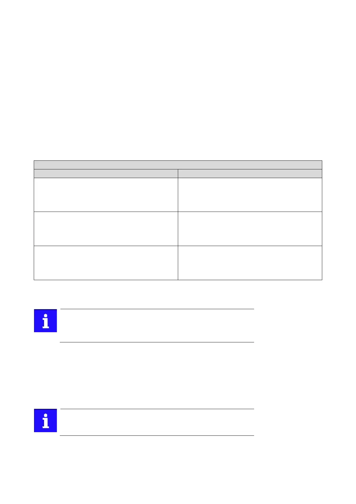
• The input and output registers are divided into three blocks (A, B, C) in each case,
featuring 4 successive data words, respectively:
Network IN B0
Network OUT B0
The terms "input" and "output" refer to the point of view of the inverter:
• Input data are transmitted by the network master and received by the inverter.
• Output data are transmitted by the inverter and received by the network master.
The exact assignment of the network registers and the number of data
words that can be transmitted cyclically varies according to the
network/communication protocol. You can find some detailed information in
the documentation for the respective communication protocol.
Data mapping
For establishing a simple network connection, the inverter provides predefined control
and status words for device profile CiA 402, AC drive profile. By means of data mapping to
a network register, each of these words can be transferred as process date via network.
Additionally, further mappable data words are provided to individually control the
inverter. The mappable data words are described in detail in the following subchapters.
Data mapping cannot be applied to all parameters. The mappable
parameters are marked correspondingly in the parameter attribute list.