12.2.6. Example 6: Enable inverter
This example shows how to use the "Enable inverter" function for a separate enable input.
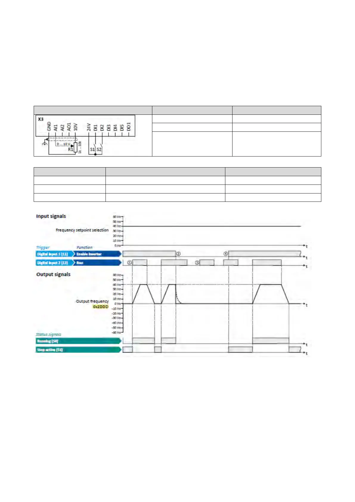
• In idle state of switch S1 (normally-closed contact), "Enable inverter" is already
available.
• Switch S2 starts the motor in forward rotating direction (if switch S1 is closed). Switch
S2 in initial position stops the motor again.
• Switch S1 disables the inverter. The motor becomes torqueless (coasts).
Potentiometer R1 Frequency setpoint selection
0x2631:004 (P400.04)
Reset fault
Not connected [0]
The status signals can be assigned to digital outputs.
Configuration of digital outputs
429
① If the inverter is enabled and no error is active, the motor can be started with the
"Run" function in forward rotating direction.
② If "Enable inverter" is set to FALSE, the inverter is disabled. The motor becomes
torqueless and coasts to standstill as a function of the mass inertia of the machine.
③ Without "Enable inverter", the motor cannot be started.
④ In the default setting, the motor does not start if the "Run" function is set to TRUE
during "Enable inverter" . After "Enable inverter", must be retriggered to start the
motor.
Starting
performance
97