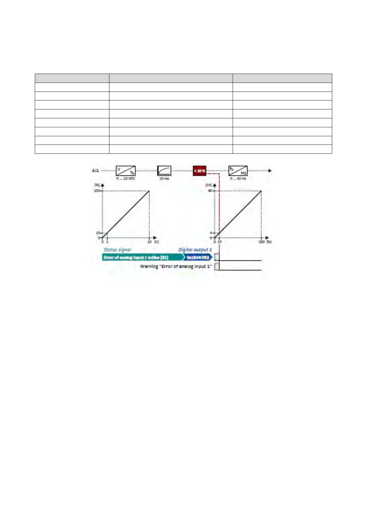
12.14.1.3. Example 3: Error detection
In this example, the digital output 1 is set via the trigger "Error of analog input 1 active
[81]" if the percentage input value is lower than 10 %. Additionally, a warning is output.
Digital outputs function: Digital output 1
Error of analog input 1 active [81]
Analog input 1: Input range
0x2636:002 (P430.02)
Analog input 1: Min frequency value
0.0 Hz
Analog input 1: Max frequency value
Analog input 1: Filter time
Analog input 1: Monitoring threshold
Analog input 1: Monitoring condition
Input value < trigger threshold [0]
0x2636:010 (P430.10)
Analog input 1: Error response
Warning [1]