8.6.7. Modbus RTU function codes
The mode of access to inverter data (parameters) is controlled via function codes.
Details
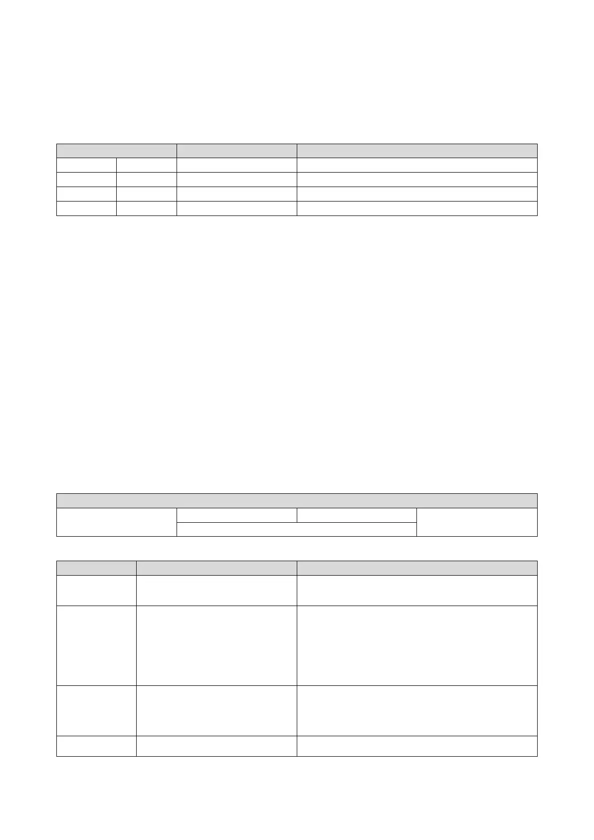
The inverter supports the following function codes:
Function code
Function name
Description
Read one or more 16-bit data words.
Write a 16-bit data word.
Preset Multiple Registers
Write one or more 16-bit data words.
Write one or more 16-bit data words and read them back.
Addressing
The function codes listed above exclusively refer to 4X registers in Modbus addressing.
All data in the inverter can only be accessed via 4X registers, i.e. via register addresses
from 40001.
The 4xxxx reference is implicit, i. e. given by the function code used. In the frame therefore
the leading 4 is omitted in the addressing process.
The numbering of the registers starts with 1; addressing, however, starts with 0. Therefore,
for instance, the address 0 is used in the frame when register 40001 is read.
Telegram structure
Communication is established on the basis of the central medium access method.
Communication is always started by a master request. The inverter (slave) then either
gives a valid response or outputs an error code (provided that the request has been
received and evaluated as a valid Modbus frame). Error causes can be invalid CRC
checksums, function codes that are not supported, or impermissible data access.
All Modbus frames have the following basic structure:
• A "frame" consists of a PDU (Protocol Data Unit) and an ADU (Application Data Unit).
• The PDU contains the function code and the data belonging to the function code.
• The ADU serves the purposes of addressing and error detection.
• The data are represented in Big Endian format (most significant byte first).
ADU (Application Data Unit)
Error codes
The function code is not supported by the inverter, or the inverter is in a
state in which the request is not permissible or in which it cannot be
The combination of a start address and the length of the data to be
transmitted is invalid.
Example: If you have a slave with 100 registers, the first register has the
address 0 and the last register has the address 99. If there is a request of
four registers now, from the start address 96, the request can be
processed successfully (for registers 96, 97, 98, and 99). If, however, five
registers from the start address 96 are queried, this error code is
returned, since the slave has no register with the address 100.
The cause, however, is not that a (parameter) value is written outside
the valid setting range. As a matter of principle, the Modbus protocol
has no information on valid setting ranges of individual registers or their
A non-correctable error has occurred while the request was processed
in the inverter.