7.4.4. Motor controller settings
After the motor settings have been made, the different control loops must be set. For a
quick commissioning, the calculations and settings are made automatically if one of the
following optimisations is carried out:
Automatic motor identification (energized)
139
Automatic motor calibration (non-energized)
140
Details
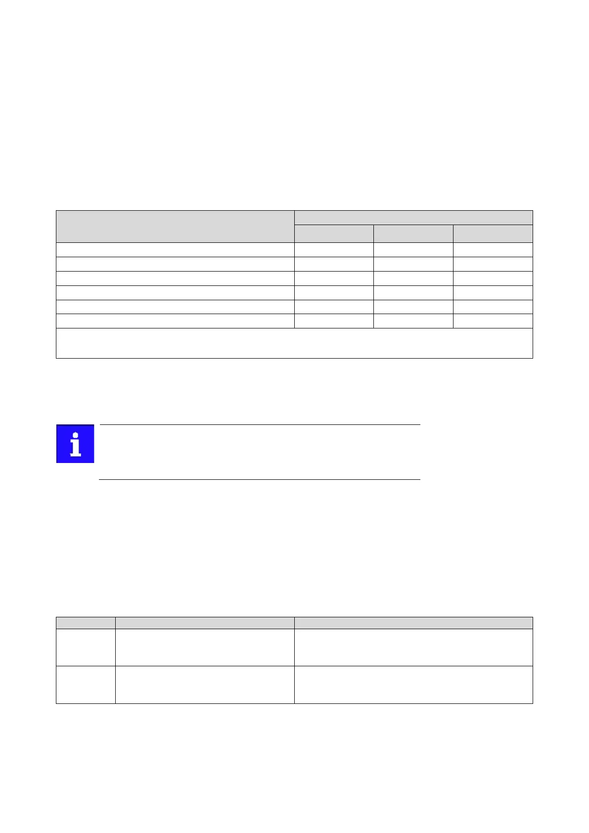
The following controllers have an influence in the respective motor control type:
143
144
Field weakening controller
144
145
Flying restart controller
146
• • •
146
VFC open loop = V/f characteristic control
SL-PSM = sensorless control for synchronous motor
SLVC = sensorless vector control
7.4.4.1. Current controller
For a quick commissioning, the calculations and settings are made automatically during
the optimisation.
For typical applications, a manual adaptation of the parameters of the
current controller is not recommended. A wrong setting may have a negative
effect on the control. For special applications, contact the manufacturer
before adapting the parameters.
Preconditions
The current controller parameters are calculated based on the stator resistance and
leakage inductance. Thus, the following parameters must be set correctly, either via
optimisation or manually (according to manufacturer-data/motor data sheet):
• 0x2C01:002: Stator resistance
• 0x2C01:003: Stator leakage inductance
Motor equivalent circuit diagram data
142
Name / value range / [default setting]
(P334.01)
Current controller parameters: Gain
(Current contr.: Gain)
0.00 ... [42.55]* ... 750.00 V/A
* Default setting depending on the size.
Gain factor Vp of the current controller.
(P334.02)
Current controller parameters: Reset time
(Current contr.: Reset time)
0.01 ... [4.50]* ... 2000.00 ms
* Default setting depending on the size.
Reset time Ti of the current controller.
7.4.4.2. Field controller
For a quick commissioning, the calculations and settings are made automatically during
the optimisation.