448 01-6203-01R3, CG Drives & Automation
12.14.2. Analog input 2
Settings for analog input 2.
Details
The analog input 2 can be used as setpoint source.
Selection of setpoint source
93
For the process controller, the analog input can be used for the feedback of the variable
(actual value) or speed feedforward control. Basic process controller settings
233
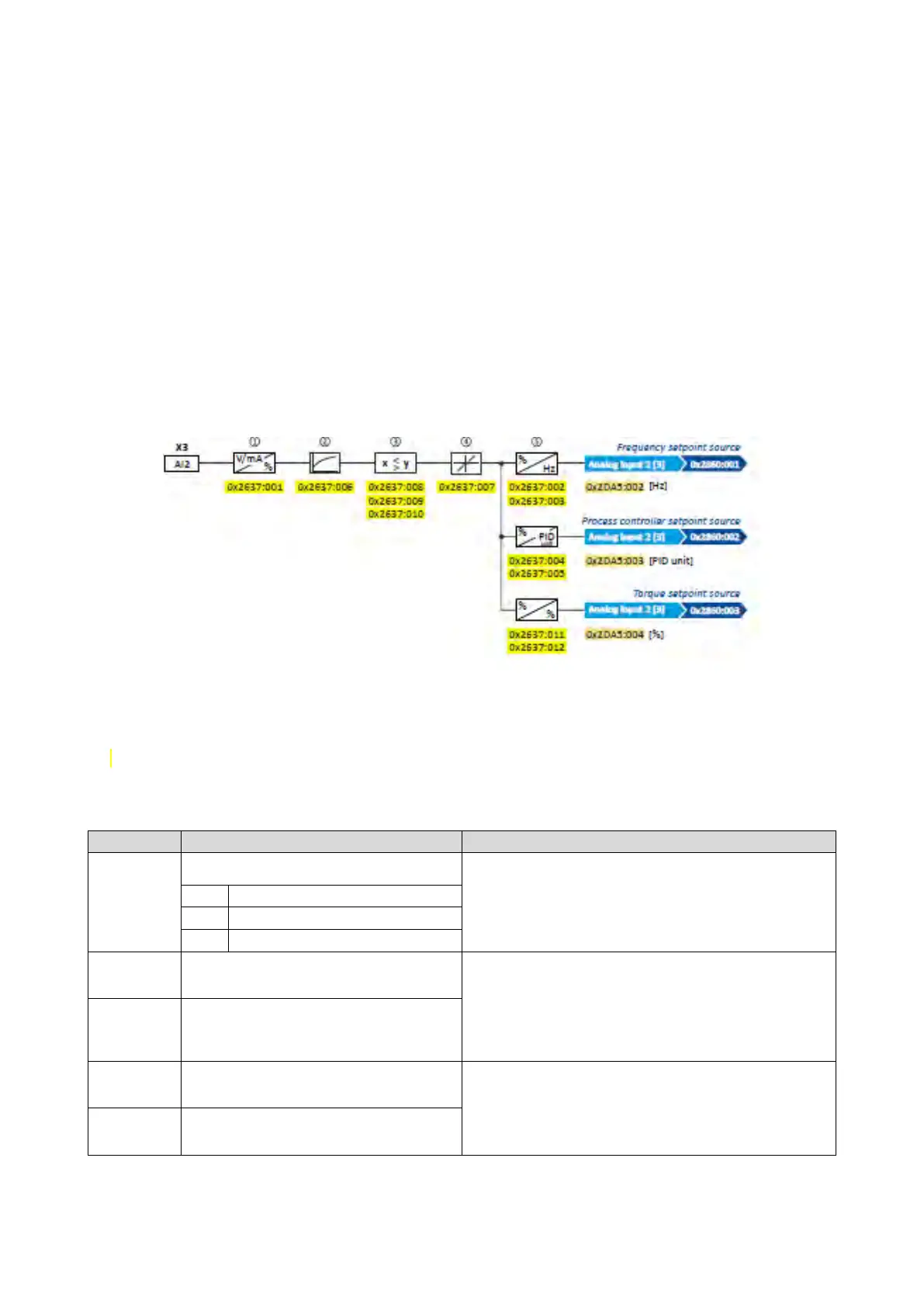
The following settings are possible for the analog input:
• Definition of the input range ①
• Filter time for low-pass filters ②
• Monitoring of the input signal ③
• Dead band for eliminating the smallest signal levels ④
• Definition of the setting range ⑤
Diagnostic parameters:
• The frequency value is displayed in 0x2DA5:002 (P111.02).
• The process controller value is displayed in 0x2DA5:003 (P111.03).
• The torque value is displayed in 0x2DA5:004 (P111.04).
For further details and configuration examples, see chapter "Analog input 1".
423
Name / value range / [default setting]
(P431.01)
Analog input 2: Input range
(Analog input 2: AI2 input range)
Definition of the input range.
0
0 ... 10 VDC
(P431.02)
Analog input 2: Min frequency value
(Analog input 2: AI2 freq @ min)
-1000.0 ... [0.0] ... 1000.0 Hz
Definition of the setting range for operating mode "MS: Velocity mode".
Direction of rotation according to sign.
The standard setpoint source for operating mode 0x6060 (P301.00) =
"MS: Velocity mode [-2]" is selected in 0x2860:001 (P201.01).
(P431.03)
Analog input 2: Max frequency value
(Analog input 2: AI2 freq @ max)
Device for 50-Hz mains: -1000.0 ... [50.0] ... 1000.0 Hz
Device for 60-Hz mains: -1000.0 ... [60.0] ... 1000.0 Hz
(P431.04)
Analog input 2: Min PID value
(Analog input 2: AI2 PID @ min)
-300.00 ... [0.00] ... 300.00 PID unit
Definition of the setting range for PID control.
The standard setpoint source for the reference value of PID control is
selected in 0x2860:002 (P201.02).
0x2637:005
(P431.05)
Analog input 2: Max PID value
(Analog input 2: AI2 PID @ max)
-300.00 ... [100.00] ... 300.00 PID unit