12.16.1.1. Example 1: Output voltage 0 ... 10 V ≡ output frequency 0 ... 100 Hz
In this configuration, a voltage is provided at the analog output proportionately to the
current output frequency of the inverter (1 V ≡ 10 Hz, resolution 0.1 Hz).
Analog output 1: Output range
Analog output 1: Function
0x2639:003 (P440.03)
Analog output 1: Min. signal
0
Analog output 1: Max. signal
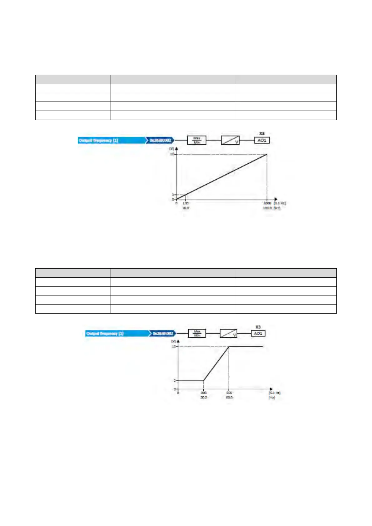
12.16.1.2. Example 2: Output voltage 2 ... 10 V ≡ output frequency 30 ... 60 Hz
In this configuration, the output range 2 ... 10 V is used for the output of the output
frequency (resolution: 0.1 Hz). The example shows how the signals outside the signal
range (here: 30 ... 60 Hz) are cut off.
Analog output 1: Output range
Analog output 1: Function
0x2639:003 (P440.03)
Analog output 1: Min. signal
300
Analog output 1: Max. signal
Output frequency [1]