338 01-6203-01R3, CG Drives & Automation
10.18. Additive voltage impression
This function serves to boost (or lower) the motor voltage from the process via an additive
voltage setpoint in order to realise a load adjustment (for instance in case of winder
applications).
NOTICE
A too high boost of the motor voltage may cause the motor to heat up strongly due to the
resulting current.
▶ Avoid a too high boost of the motor voltage!
Details
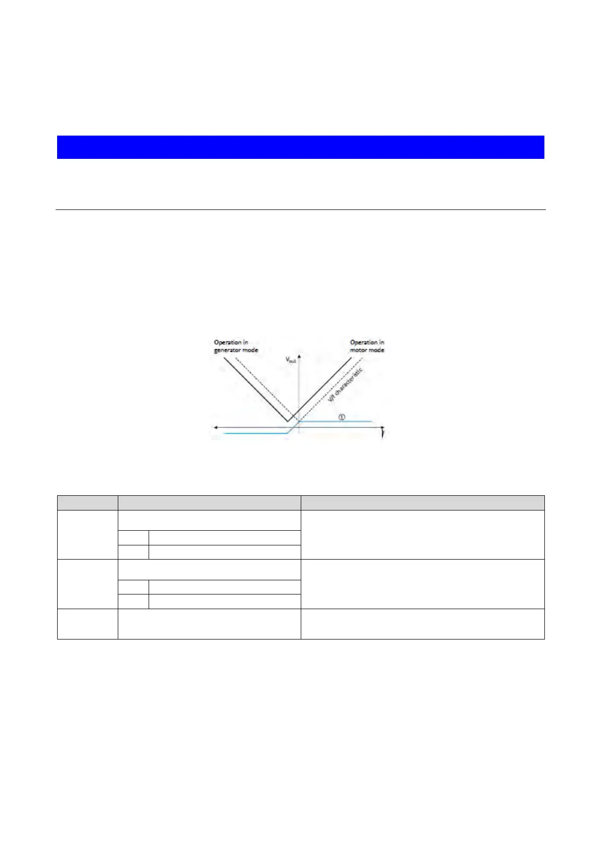
At a constant field frequency, the output voltage of the inverter can be changed within a
wide range.
Example: Adaptation of the voltage characteristic in case of V/f characteristic control as a
function of the load:
• Clockwise rotation (CW) is operation in motor mode: Boost voltage.
• Counter-clockwise rotation (CCW) is operation in generator mode: Lower voltage.
① Selecting an additive voltage setpoint
A detailed configuration example for this function can be found in the following
subchapter.
Name / value range / [default setting]
0x2B13:001
Additive voltage impression: Enable Function
1 = enable function.
0x2B13:002
Additive voltage impression: Setpoint source
Selection of the source for specifying the additive voltage setpoint.
•
100 % ≡ Rated voltage 0x2C01:007 (P320.07)
1
Analog input 1
Additive voltage impression: Actual voltage
Read only: x V
Display of the current (boosted or lowered) voltage.