174 01-6203-01R3, CG Drives & Automation
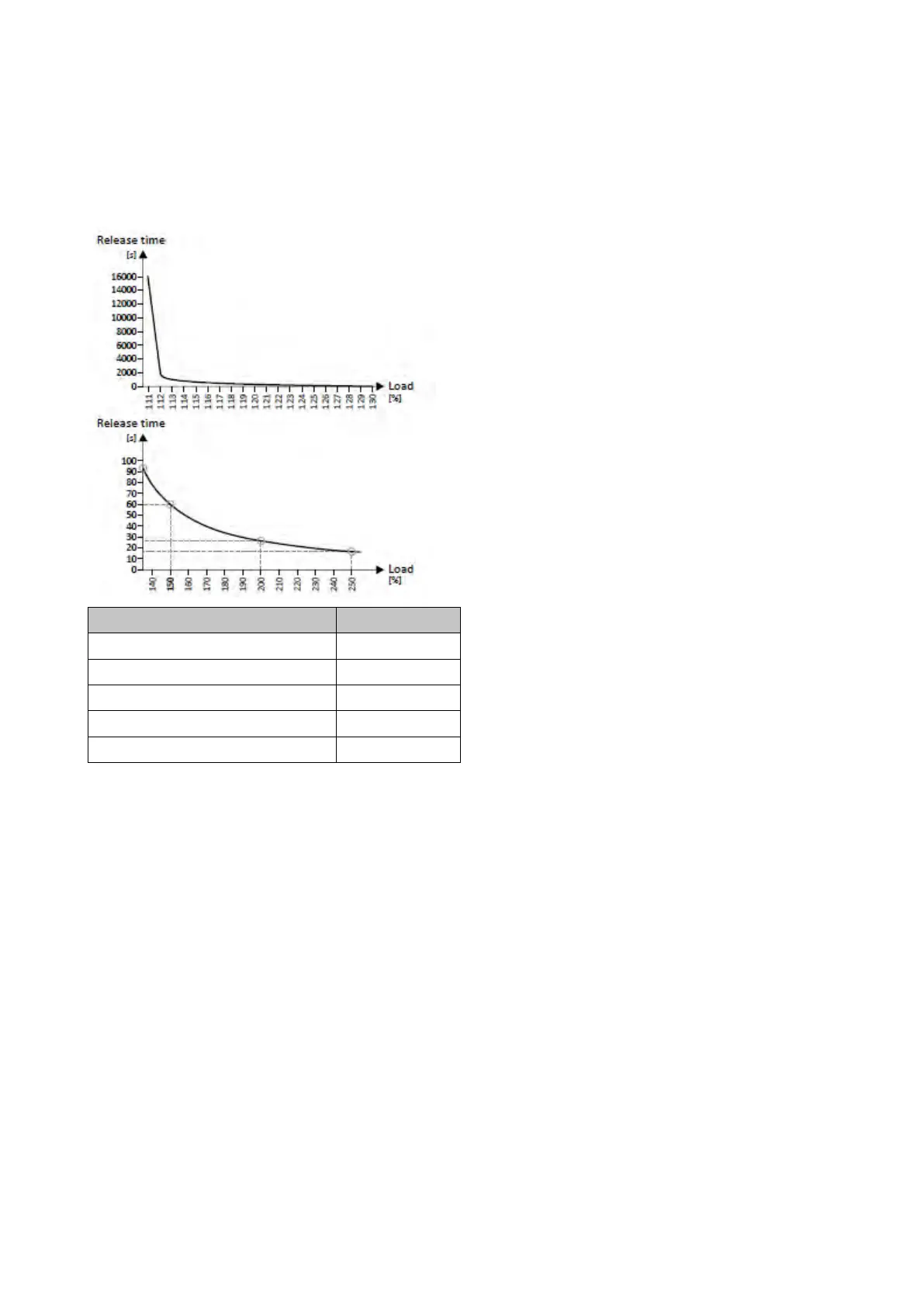
The following two diagrams show the relation between the motor load and release time of the monitoring
under the following conditions:
• Maximum utilisation 0x2D4B:001 (P308.01) = 150 %
• Speed compensation 0x2D4B:002 (P308.02) = "Off [1]" or output frequency ≥ 40 Hz
Load * Load ratio Release time
110 % Indefinite
135 % 93 s
150 % 60 s
200 % 26 s
250 % 17 s
Depending on the setting in 0x2D4B:001 (P308.01), the release time from the diagrams
can be derived as follows:
• Calculation of the load ratio:
Load ratio = 150 % / maximum utilisation 0x2D4B:001 (P308.01) (example: 0x2D4B:001
(P308.01) = 75 %
à
load ratio = 150 % / 75 % = 2)
• Calculation of the release time of the monitoring:
Release time = actual load * load ratio
(example: actual load = 75 %
à
release time = 75 % * 2 = 150 %)
• Looking up the release time from the above table based on load * load ratio.
(example: Load * load ratio = 150 %
à
release time = 60 s)