General mode of operation
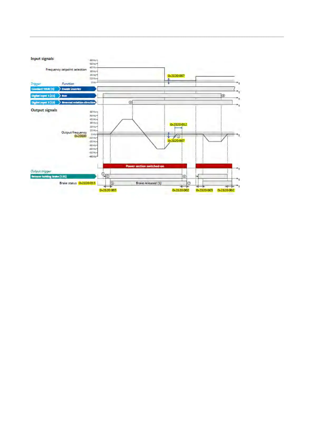
The following diagram demonstrates the general functioning in automatic operation:
① If the inverter is enabled and no error is active, the motor can be started with the
"Run" function in forward rotating direction.
The power section is switched on and the motor is magnetised first.
② The holding brake is released. For this purpose, the output trigger "Release holding
brake [115]" is set to TRUE. This trigger must be assigned to a digital output or, in the
simplest case, to the relay which then switches the brake supply.
③ After the release time 0x2820:003 (P712.03) has elapsed, the motor is accelerated to
the setpoint.
The brake status "Brake released [1]" is displayed in 0x2820:015 (P712.15).
④ If the direction of rotation reverses, the holding brake remains released (even if the
closing threshold delay is running.)
⑤ If the setpoint selection and the internal setpoint for the motor control fall below the
brake closing threshold set in 0x2820:007 (P712.07), the output frequency is ramped
down to "0 Hz".
At the same time the closing threshold delay set in 0x2820:012 (P712.12) starts to
run
⑥ If the values fall below the closing threshold longer than the closing threshold delay,
the holding brake is closed again.
⑦ After the closing time 0x2820:002 (P712.02) has elapsed, the brake status "Active
[0]" is displayed in 0x2820:015 (P712.15).
⑧ If "Run" is set to FALSE, the motor is stopped with the stop method set in 0x2838:003
(P203.03). In the example: Stop with standard ramp.
In this case, closing threshold and closing threshold delay are not effective anymore.
 Loading...

