EPSON EPL-N3000/AcuLaser M4000N Revision C
Troubleshooting Troubleshooting for Individual Units 118
Confidential
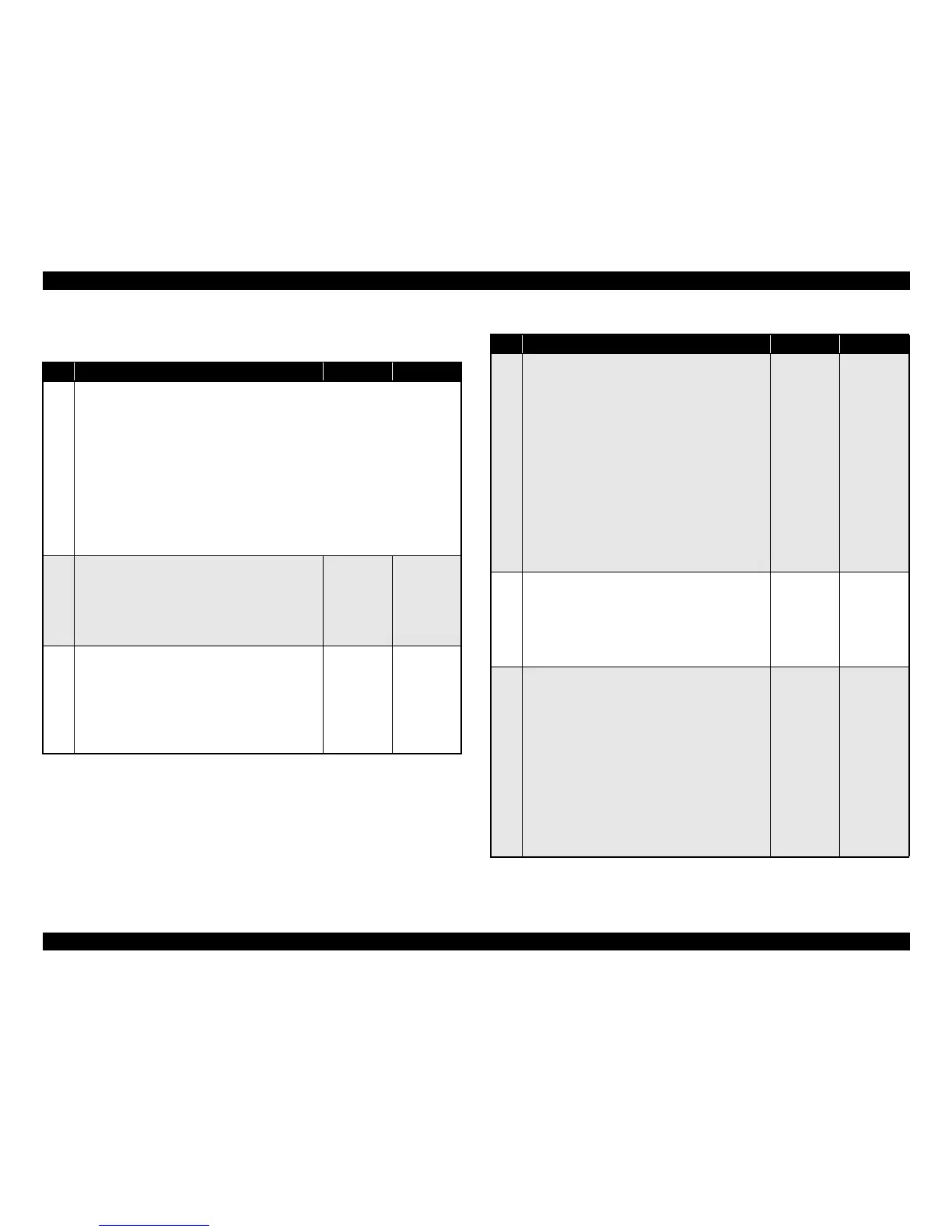
3.4.6 SENSOR NO PAPER
Table 3-65. Troubleshooting for SENSOR NO PAPER
Step Action and Question Yes No
Parts below can be the source of this error (Chapter 4 Disassembly and Assembly)
• SENSOR NO PAPER (p.222), (p.232)
• ACTUATOR NO PAPER (p.223), (p.238)
• 150 FEEDER ASSY (p.211)
• HARNESS ASSY TRAY1
• HARNESS ASSY TRAY2
• HARNESS ASSY CHUTE
•HVPS/MCU (p.301)
• PLATE ASSY BTM (p.330)
•LVPS (p.287)
• 550 FEEDER ASSY (p.224)
1
ACTUATOR NO PAPER
♦Does the ACTUATOR NO PAPER move smoothly
when moved with your finger, furthermore, does the
flag go into the sensor area when paper is present
and move down from the sensor when paper is not
present?
Go to Step 2
Replace the
ACTUATOR
NO PAPER
2
PLATE ASSY BTM
1. Install the Paper Cassette containing no paper.
2. Check the relationship between the flag of the
ACTUATOR NO PAPER and the detecting point of
the sensor.
♦Is the flag of the ACTUATOR NO PAPER
positioned in the sensing area of the sensor?
Go to Step 3
Replace the
PLATE ASSY
BTM
3
SENSOR NO PAPER(1)
1. Remove the Imaging Cartridge.
2. Close the COVER OPEN.
3. Remove the Paper Cassette.
4. Insert your hand through the tray insertion opening
and while moving the ACTUATOR NO PAPER up
and down with your hand, measure the voltage
between P/J24-8
↔ P/J24-7 and between P/J24-3 ↔
P/J24-2 on the HVPS/MCU.
(Refer to “Connectors (p.406)”)
♦Is the voltage 0 VDC between P/J24-8 ↔ P/J24-7
and between P/J24-3 ↔ P/J24-2 when the
ACTUATOR NO PAPER has moved up and 3.3
VDC when the ACTUATOR NO PAPER has
moved down?
Replace the
HVPS/MCU
Go to Step 4
4
Power supply to the SENSOR NO PAPER
1. Remove the Imaging Cartridge.
2. Check the voltage between P/J24-8 ↔ P/J24-7 and
between P/J24-3
↔ P/J24-2 on the HVPS/MCU.
♦Is the voltage 3.3 VDC between P/J24-8 ↔ P/J24-7
and between P/J24-3
↔ P/J24-2?
Go to Step 5 Go to Step 7
5
Continuity of the HARNESS ASSY CHUTE
1. Disconnect the connector P/J24 on the HVPS/MCU.
2. Disconnect P/J245 and P/J248.
3. Check continuity of the following wiring:
J24-6 ↔ J245-13
J24-7 ↔ J245-12
J24-8 ↔ J245-11
J24-1 ↔ J248-5
J24-2 ↔ J248-4
J24-3 ↔ J248-3
♦Does each wiring between J24 ↔ J245 and between
J24 ↔ J248 have continuity?
Go to Step 6
Replace the
HARNESS
ASSY
CHUTE
Table 3-65. Troubleshooting for SENSOR NO PAPER
Step Action and Question Yes No