EPSON EPL-N3000/AcuLaser M4000N Revision C
Disassembly and Assembly 550 Paper Cassette 207
Confidential
4.4.8 GUIDE INDICATOR 3
Removal
1. Remove the COVER CST from the cassette body.
2. Remove the HANDLE EXTENSION 550. (p.206)
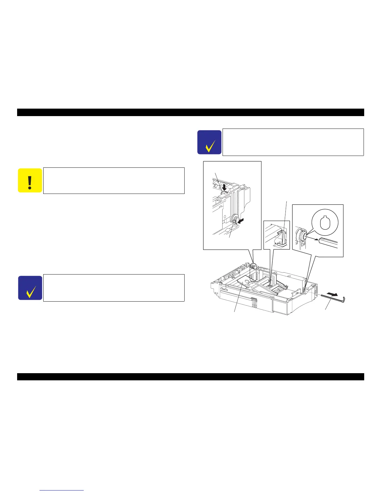
3. While pushing the lock of the STOPPER GEAR, unlock the LEVER BTM LOCK,
and raise the PLATE ASSY BTM.
4. Move away the link lever of the GUIDE INDICATOR 1, and remove it from the
PLATE ASSY BTM.
5. With the link lever pushed down to the bottom of the cassette, pull out the GUIDE
INDICATOR 3 from the front of the HOUSING EXTENSION 550 slowly by
application of force.
Installation
1. With the link lever pushed down to the bottom of the cassette, install the GUIDE
INDICATOR 3 from the front of the HOUSING EXTENSION 550.
2. Insert the link lever of the GUIDE INDICATOR 1 into the hole of the PLATE
ASSY BTM.
3. Install the LOW IND FRONT. (p.210)
4. Install the HANDLE EXTENSION 550. (p.206)
5. Install the COVER CST to the cassette body.
Figure 4- 36. GUIDE INDICATOR 3 Removal
C A U T I O N
When removing the HANDLE EXTENSION 550, take care not to
mislay the LOW INDICATOR and LOW IND FRONT as they will
come off.
C H E C K
P O I N T
Match the groove of the GUIDE INDICATOR 1 and the protrusion
part of the GUIDE INDICATOR 3.
C H E C K
P O I N T
After completion of assembling, move the PLATE ASSY BTM up/
down, and make sure that the LOW IND FRONT moves up/down
synchronously.
JG3027A