EPSON EPL-N3000/AcuLaser M4000N Revision C
Disassembly and Assembly AcuLaser M4000N Unique Disassembly Procedures 388
Confidential
4.14.6 MAIN MOTOR (AcuLaser M4000N)
Removal
1. Remove the COVER REAR 500. (p.270)
2. Remove the COVER REAR (AcuLaser M4000N). (p.379)
3. Remove the FUSER ASSY. (p.253)
4. Remove the COVER LEFT. (p.169)
5. Remove the COVER RIGHT. (p.168)
6. Remove the COVER EXIT 500. (p.261)
7. Remove the 500 EXIT ASSY. (p.262)
8. Remove the COVER TOP, CONTROL PANEL (AcuLaser M4000N). (p.380)
9. Remove the COVER FRONT. (p.172)
10. Remove the BTR ASSY. (p.254)
11. Remove the DUCT FRONT, FAN SUB. (p.241)
12. Remove the ROS ASSY (AcuLaser M4000N). (p.386)
13. Remove the SHIELD PLATE ROS. (p.243)
14. Remove the GUIDE TRAY LEFT. (p.236)
15. Remove the MOTOR COVER. (p.277)
16. Remove the SHIELD PLATE LVPS. (p.285)
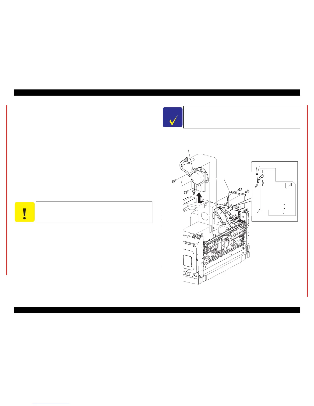
17. Disconnect the connector (P/J43) of the MAIN MOTOR from the LVPS.
18. Disconnect the connector (P/J271) of the MAIN MOTOR from the relay
connector.
19. Lift the 150 FEEDER ASSY.
20. Remove the three screws (gold, 6mm) securing the MAIN MOTOR to the frame.
21. Remove the MAIN MOTOR.
Figure 4- 179. MAIN MOTOR Removal
C A U T I O N
Never give impact to the ROS ASSY with a screwdriver or the like.
C H E C K
P O I N T
The 150 FEEDER ASSY clicks midway when lifted, but lift it by
application of slight force.
J23179EA
LVPS
SHIELD PLATE
LVPS
P/J43
P/J271
MAIN MOTOR
19)
20)
17)