EPSON EPL-N3000/AcuLaser M4000N Revision C
Troubleshooting Troubleshooting for Individual Units 126
Confidential
3.4.16 HVPS/MCU
Table 3-75. Troubleshooting for HVPS/MCU
Step Action and Question Yes No
Parts below can be the source of this error (Chapter 4 Disassembly and Assembly)
•HVPS/MCU (p.301)
• GUIDE ASSY CRU R (p.257)
• Imaging Cartridge
• HARNESS ASSY ANT
• HARNESS ASSY LVPS
1
Power supply by GUIDE ASSY CRU R
1. Check to see if the GUIDE ASSY CRU R is
installed properly.
♦Check if the GUIDE ASSY CRU R is installed
properly.
♦Check if the GUIDE ASSY CRU R contacts with
the HVPS/MCU and the plate of the Imaging
Cartridge properly.
♦Check if the HVPS/MCU is assembled to under the
hook of the FRAME.
Go to Step 2
Replace the
GUIDE ASSY
CRU R
2
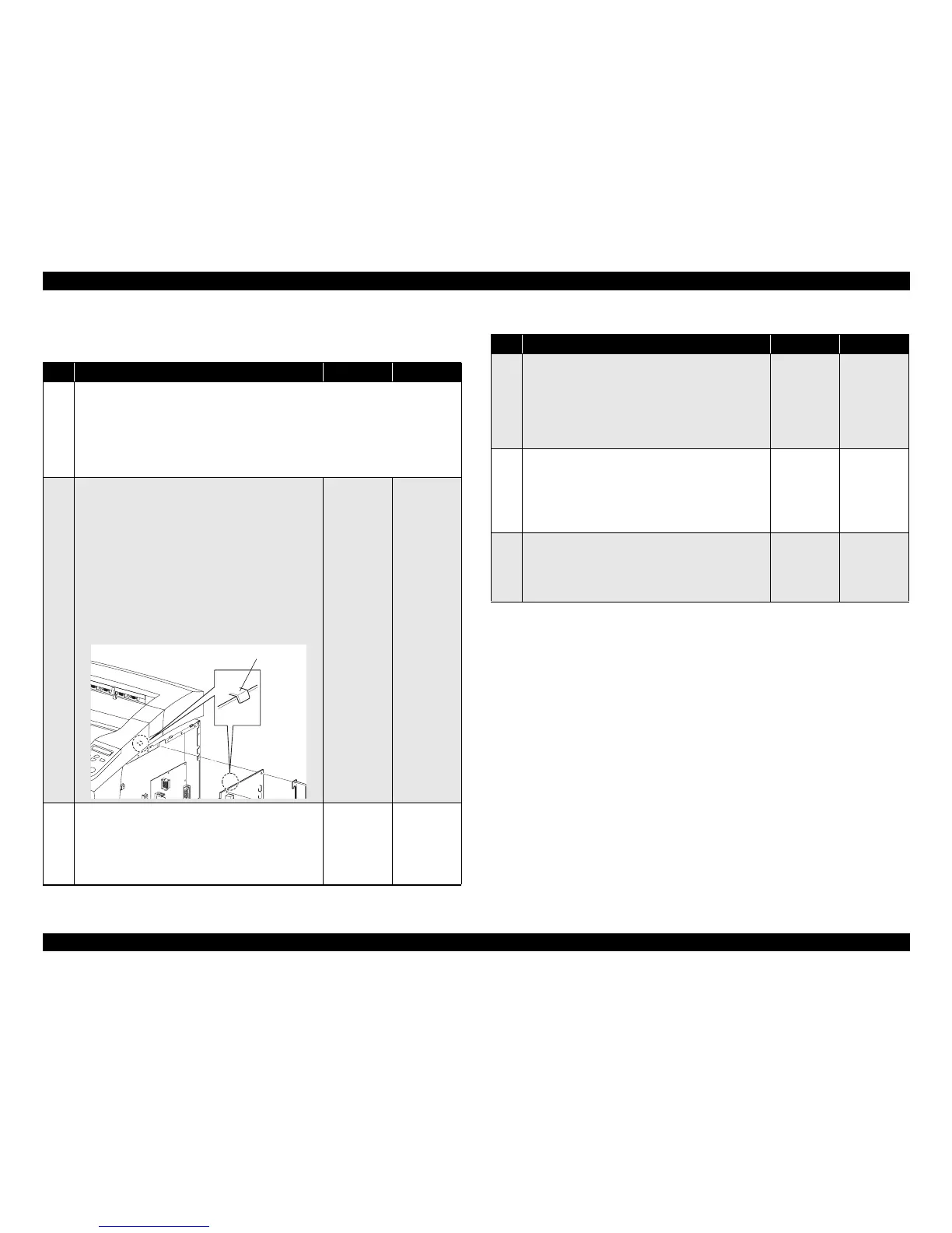
GUIDE ASSY CRU R
1. Remove the GUIDE ASSY CRU R. (p.257)
2. Check the Plate Earth of the GUIDE ASSY CRU R.
♦Is the Plate Earth free from deformation, dirt and
damage?
Go to Step 3
Replace the
GUIDE ASSY
CRU R
JG54A7AA
HOOK
Note1
3
24V power supply to the HVPS/MCU
1. Remove the Imaging Cartridge.
2. Measure the voltage between P/J10-1 ↔ P/J10-4 on
the HVPS/MCU.
(Refer to “Connectors (p.406)”)
♦24V between P/J10-1 ↔ P/J10-4?
Go to Step 5 Go to Step 4
4
Continuity of the HARNESS ASSY LVPS
1. Disconnect the connector P/J10 on the HVPS/MCU.
2. Disconnect the connector P/J42 on the LVPS.
3. Check continuity between P/J10 ↔ P/J42.
♦Is there continuity between P/J10 ↔ P/J42?
Go to 3.4.1
LVPS (p.111)
Replace the
HARNESS
ASSY LVPS
5
HARNESS ASSY ANT
1. Disconnect the connector P/J15 on the HVPS/MCU.
2. Check continuity between J15 ↔ J150.
♦Is there continuity between J15 ↔ J150?
Replace the
HVPS/MCU
Replace the
HARNESS
ASSY ANT
Table 3-75. Troubleshooting for HVPS/MCU (continued)
Step Action and Question Yes No