EPSON EPL-N3000/AcuLaser M4000N Revision C
Disassembly and Assembly Electrical 301
Confidential
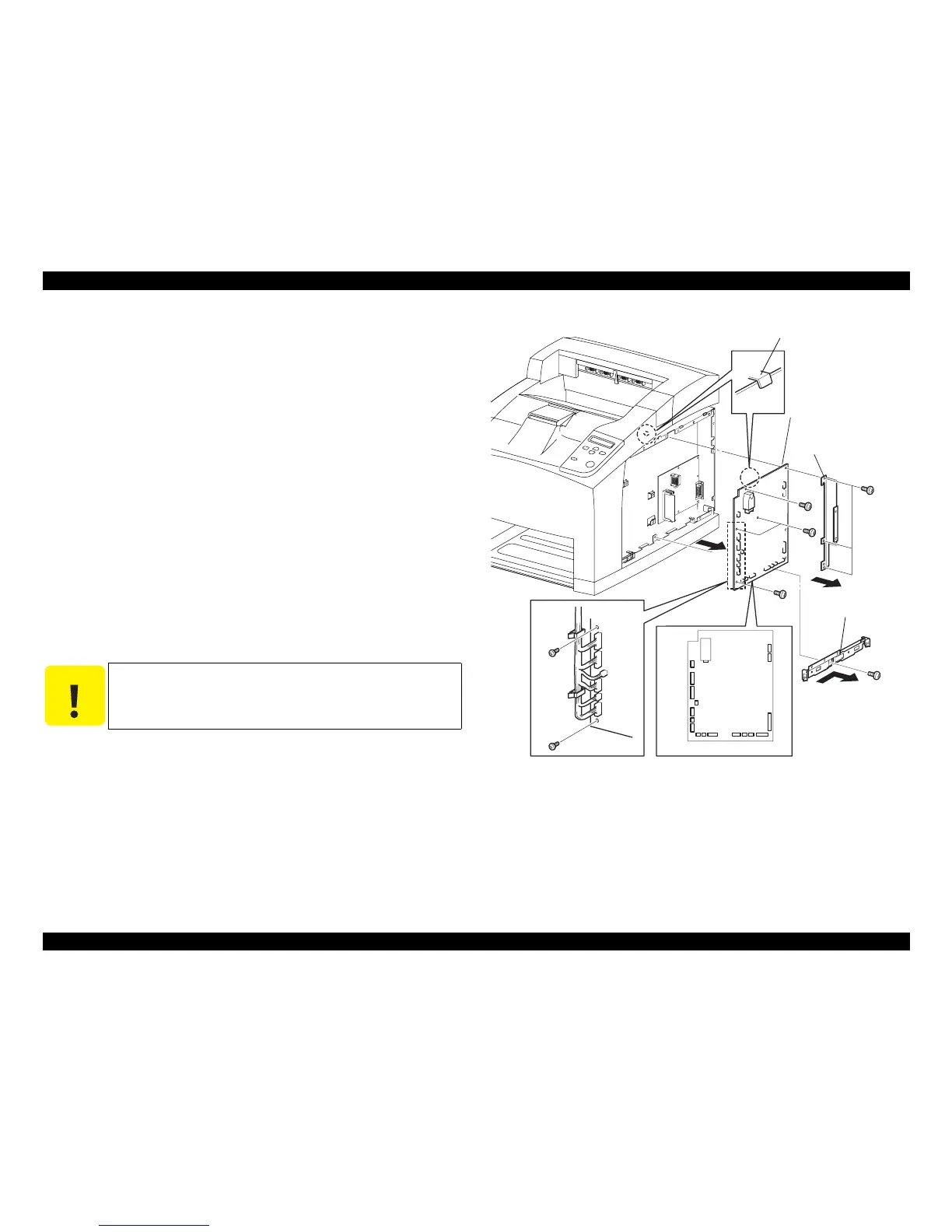
4.10.13 HVPS/MCU
Removal
1. Remove the COVER RIGHT. (p.168)
2. Remove the SHIELD ASSY ESS. (p.294)
3. Remove the SHIELD PLATE HVPS. (p.296)
4. Remove the one screw (silver, 6 mm) securing the BRACKET HANDLE R.
5. Remove the BRACKET HANDLE R from the frame.
6. Disconnect the harness connectors from the connectors (P/J10, P/J11, P/J13, P/
J14, P/J15, P/J16, P/J17, P/J18, P/J20, P/J22, P/J24, P/J26, P/J27, P/J28, P/J29, P/
J30, P/J31) of the HVPS/MCU.
7. Remove the three screws (silver, 6mm) securing the BRACKET SHIELD HVPS
to the frame.
8. Remove the BRACKET SHIELD HVPS.
9. Remove the four screws (silver, 6mm) securing the HVPS/MCU to the frame.
10. Remove the HVPS/MCU.
Installation
1. Install the HVPS/MCU to the frame with the four screws (silver, 6mm).
2. Connect the connectors (P/J10, P/J11, P/J13, P/J14, P/J15, P/J16, P/J17, P/J18, P/
J20, P/J22, P/J24, P/J26, P/J27, P/J28 P/J29, P/J30 and P/J31) of the harness to the
connectors of the HVPS/MCU.
3. Install the BRACKET SHIELD HVPS to the frame with the three screws (silver,
6mm).
4. Install the BRACKET HANDLE R with the one screw (silver, 6mm).
5. Install the SHIELD PLATE HVPS. (p.296)
6. Install the SHIELD ASSY ESS. (p.294)
7. Install the COVER RIGHT. (p.168)
Figure 4- 106. HVPS/MCU Removal
C A U T I O N
When installing the HVPS/MCU, place the circuit board under
the hook of the frame.
When tightening the screws, take care not to catch the harness.
JG3026EA
HVPS / MCU
BRACKET SHIELD HVP