EPSON EPL-N3000/AcuLaser M4000N Revision C
Disassembly and Assembly Xero 245
Confidential
4.7.4 GUIDE CRU LEFT
Removal
1. Remove the COVER REAR 500. (p.270)
2. Remove the COVER REAR. (p.167)
3. Remove the COVER LEFT. (p.169)
4. Remove the COVER RIGHT. (p.168)
5. Remove the COVER EXIT 500. (p.261)
6. Remove the 500 EXIT ASSY. (p.262)
7. Remove the COVER TOP, CONTROL PANEL. (p.170)
8. Remove the COVER FRONT. (p.172)
9. Remove the FUSER ASSY. (p.253)
10. Remove the BTR ASSY. (p.254)
11. Remove the GUIDE TRAY LEFT. (p.236)
12. Remove the DUCT FRONT, FAN SUB. (p.241)
13. Remove the ROS ASSY. (p.239)
14. Remove the SHIELD PLATE ROS. (p.243)
15. While lifting the 150 FEEDER ASSY, remove the MOTOR COVER. (p.277)
16. Remove the SHIELD PLATE LVPS. (p.285)
17. Remove the MOTOR COVER. (p.277)
18. Disconnect the connector (P/J4647) of the HARNESS ASSY FUSER from the
frame.
19. Release the clamp securing the HARNESS ASSY FUSER, which comes out of the
GUIDE CRU LEFT, to the frame to release the clamped harness.
20. Disconnect the connector (P/J141) of the INTERLOCK S/W 5V from the
HARNESS ASSY LVPS.
21. Disconnect the connector (P/J45) of the INTERLOCK S/W 24V from the LVPS.
22. Disconnect the connectors (P/J46 and P/J47) of the HARNESS ASSY FUSER
from the LVPS.
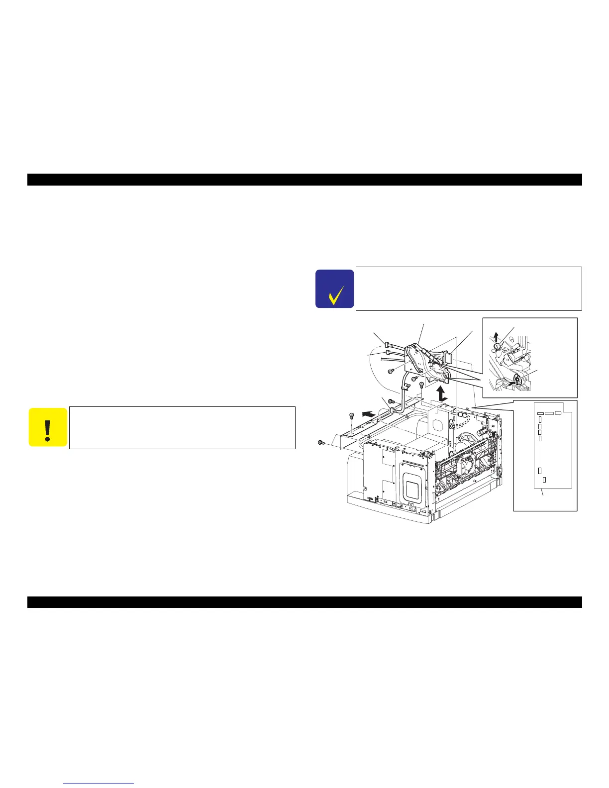
23. Remove the three screws (gold, 6 mm) securing the GUIDE CRU LEFT.
24. Remove the GUIDE CRU LEFT from the frame.
Figure 4- 62. GUIDE CRU LEFT Removal
C A U T I O N
Never give impact to the ROS ASSY with a screwdriver or the like.
C H E C K
P O I N T
Remove the GUIDE CRU LEFT while simultaneously pushing the
LINK GEAR 3 in the direction of the arrow to make the removal of
the GUIDE CRU LEFT easier.
JG3191AA
GUIDE ASSY CRU L
(P/J 4647)
(P/J 45)
(P/J 46)
(P/J 47)
LINK LEVER
LINK GEAR 3
NOTE)
LVPS
46
47
P/J45
23)
20)
17)
21-1)
22)
18)
21-2)
(NOTE 1)