EPSON EPL-N3000/AcuLaser M4000N Revision C
Operating Principles Functions of Major Components 47
Confidential
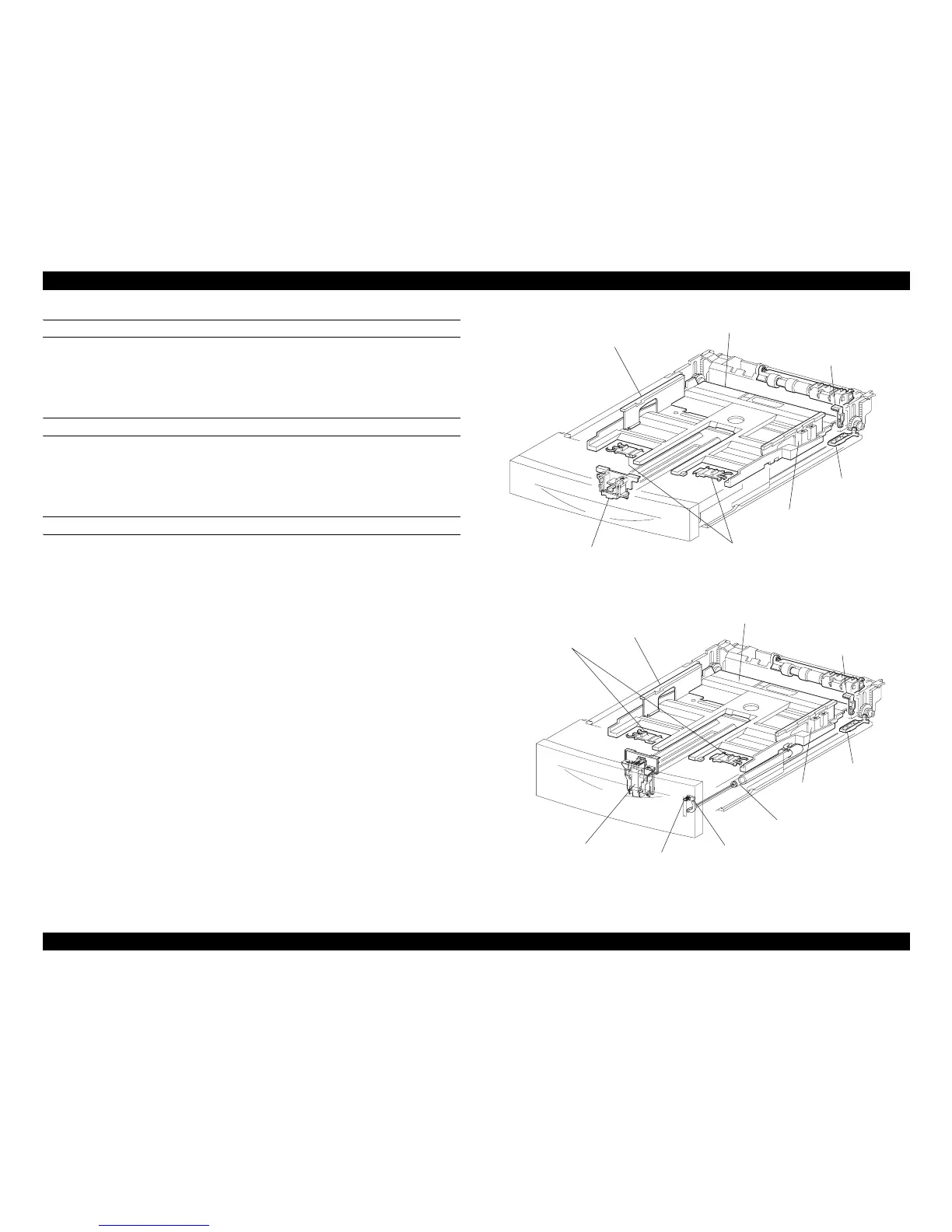
LEVER BTM LOCK AND STOPPER GEAR
These parts are located at the rear end (front end in the paper advance direction) of the
cassette. When the cassette is installed in the printer, the projection of the Feeder pushes
the LEVER BTM LOCK, the RACK BTM LOCK 150 slides, the GEAR PINION is
unlocked, and at the same time, the GEAR PB R of the STOPPER GEAR is unlocked.
PLATE ASSY BTM
The force to push up the PLATE ASSY BTM is supplied from the SPRING BTM
UP150 when the LEVER BTM LOCK and STOPPER GEAR are released from the
lock position. When the PLATE ASSY BTM is pushed up, the sheet to be fed comes in
contact with the ROLL ASSY NUDGER.
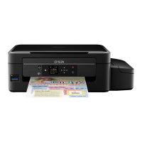
LOW INDICATOR
Mounted on the 550 Paper Cassette only, the LOW INDICATOR indicates the
remaining amount of paper in the 550 Paper Cassette with the up/down motion of the
LOW IND FRONT.
When the paper gets low, the PLATE ASSY BTM rises, and the LOW IND FRONT
lowers synchronously via the GUIDE INDICATOR.
Figure 2-23. 150 Paper Cassette
Figure 2-24. 550 Paper Cassette
LEVER BTM LOC