14
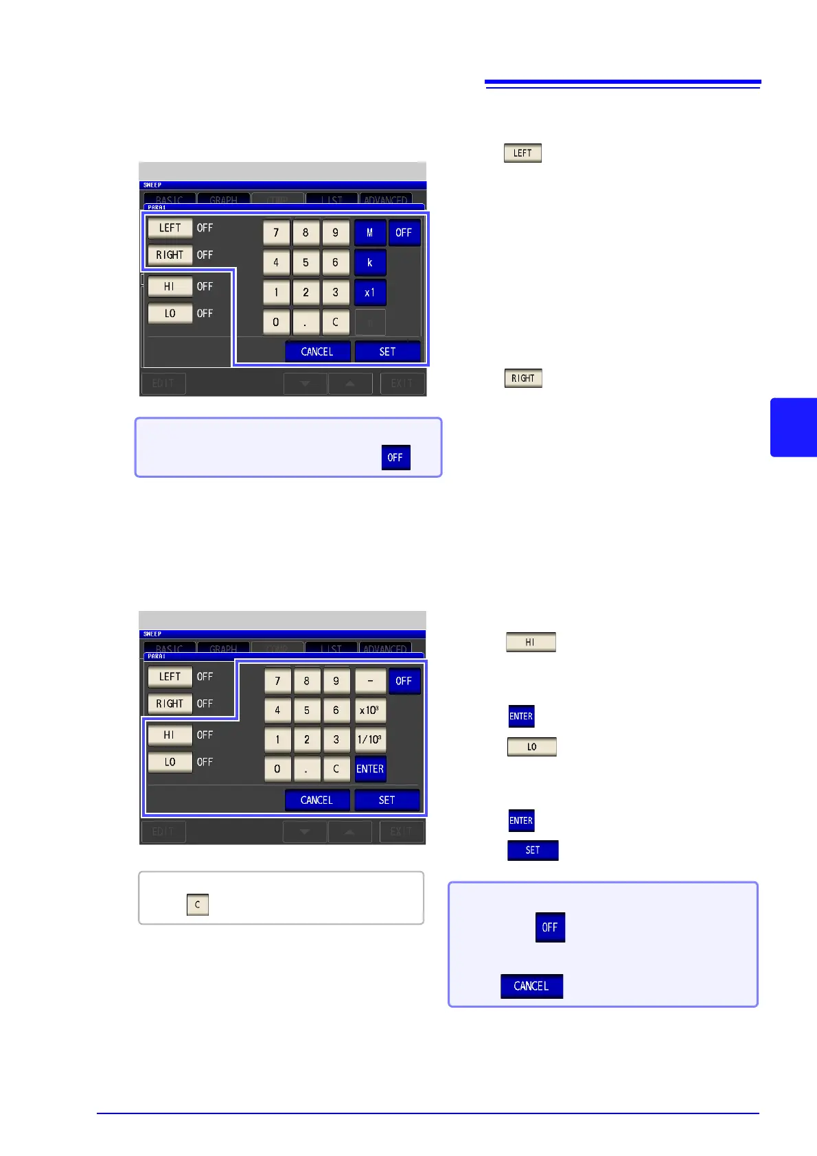
Use the numeric keypad to set the left, right, upper, and lower limit values.
1. Press and use the numeric keypad to enter the
left limit value.
The possible setting range differs depending on the
sweep parameter.
Refer to the following for each of the parameters.
• Frequency: (p. 41)
• Open circuit voltage level: (p. 43)
• Voltage level between test sample terminals:
(p. 43)
• Current level between test sample terminals:
(p. 43)
2. Press a unit key to confirm the setting.
3. Press and use the numeric keypad to enter the
right limit value.
The possible setting range differs depending on the
sweep parameter.
Refer to the following for each of the parameters.
• Frequency: (p. 41)
• Open circuit voltage level: (p. 43)
• Voltage level between test sample terminals:
(p. 43)
• Current level between test sample terminals:
(p. 43)
4. Press a unit key to confirm the setting.
Left/Right Limit Value Settings
When you do not want to set the left, right,
upper, and lower limit values: Press .
If you make a mistake during input:
press to cancel the input and start again.
Upper/Lower Limit Value Settings
5. Press and use the numeric keypad to set
the upper limit value.
Settable range: -9.999999G to 9.999999G
6. Press to confirm the setting.
7. Press and use the numeric keypad to set
the lower limit value.
Settable range: -9.999999G to 9.999999G
8. Press to confirm the setting.
9. Press to confirm the setting.
When you want to cancel the setting:
Press .
When you do not want to set a judgment
area: Press .