13.1 General Specifications
389
13
Chapter 13 Specifications
Low Z High Accuracy Mode Improves measurement accuracy in the 100 m and 1 ranges of 100 kHz or less.
• The influence of contact resistance is reduced by changing to a circuit configuration that
sets the Lp terminal to 0 V.
• The measurement current is increased (maximum 100 mA, maximum applied voltage 1
V) and the measurement accuracy is improved by setting the output resistance to 10
.
• A contact check (disconnection detection) can be performed for four terminals.
• Cable length compensation is for only 0 m and 1 m.
1 year
At least 60 minutes
Approx. 0.5 ms (100 kHz, representative value, LCD display OFF)
FAST, MED, SLOW, SLOW2
4-terminal structure
Period of guaranteed
accuracy
Warm-up time
Measurement time
Measurement speed
Terminal structure
Backup battery life
Product warranty period
Approx. 10 years (25C (77F) reference value)
1.Basic Specifications
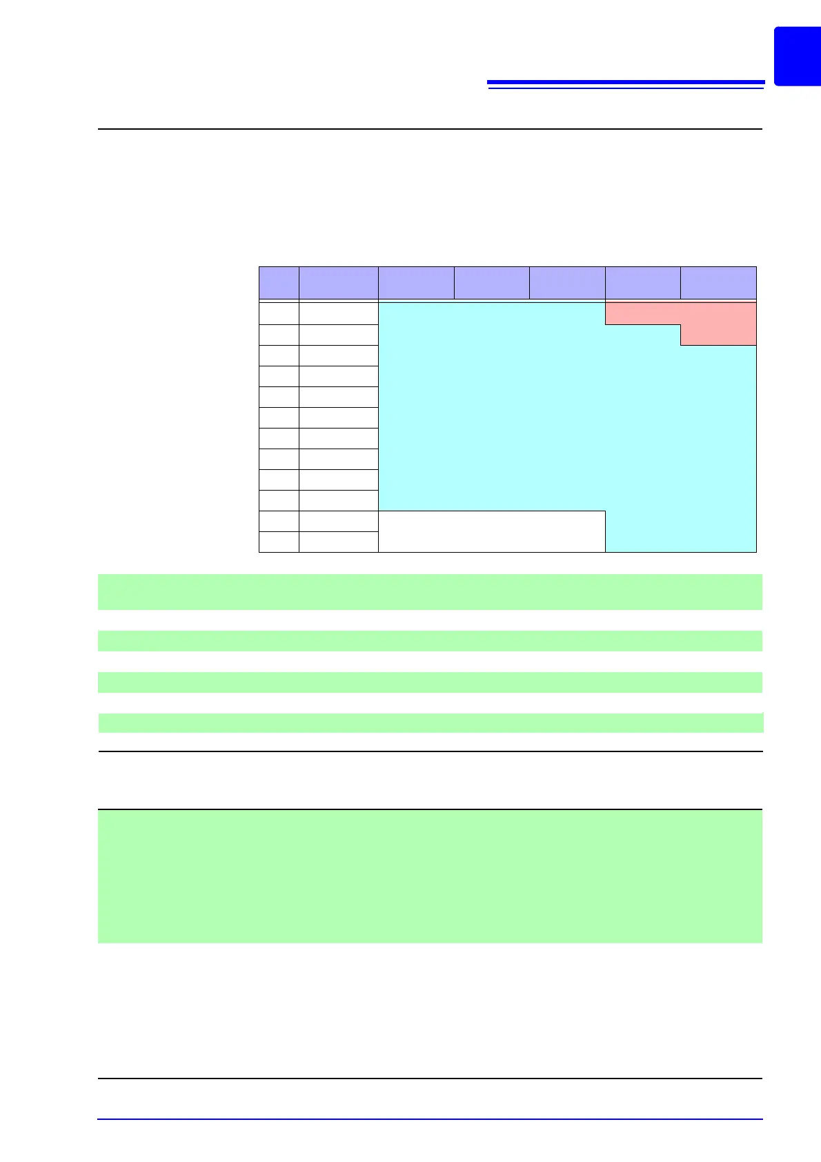
Setting range of low Z high accuracy mode
No
Measurement
range
to 1 kHz to 10 kHz to 100 kHz to 1 MHz to 5 MHz
1 100 M
2 10 M
3 1 M
4 100 k
5 30 k
6 10 k
7 3 k
8 1 k
9 300
10 10
11 1
12 100 m
Normal mode only (setting not possible for low Z high accuracy mode).
None
Low Z high accuracy mode/normal mode
2.Function
Monitor functions (1) Monitor voltage
• Monitor range 0.000 V to 5.000 V
• Monitor accuracy ±10% rdg. ±10 mV (up to 1.0000 MHz)
±20% rdg. ±10 mV (from 1.0001 MHz)
(2) Monitor current
• Monitor range 0.000 mA to 100.0 mA
• Monitor accuracy
±10% rdg. ±10 A (up to 1.0000 MHz)
±20% rdg. ±10 A (from 1.0001 MHz)
Limit function (1) Current limit (when V or CV)
• Limit range 10 A to 100.00 mA
• Limit accuracy
±10% rdg. ±10 A (up to 1.0000 MHz)
±20% rdg. ±10 A (from 1.0001 MHz)
(2) Voltage limit (when CC set)
• Limit range 0.005 V to 5.000 V
• Limit accuracy
±10% rdg. ±10 mV (up to 1.0000 MHz)
±20% rdg. ±10 mV (from 1.0001 MHz)
3 year