REV 0, June 2005 Page 129
Operation Manual SUPREMA
5. Installation
Writing Object directory 16*1+4+1536=1556=
614
(hex) Net1<-Net0
Nodegard 16*1+4+1792=1812=
714
(hex) Net1<-Net0
Digital Output 16*0+14+512=526=
20E
(hex) Net1<-Net
Writing Object directory 16*0+14+1536=1550=
60E
(hex) Net1<-Net
Nodegard 16*0+14+1792=1806=
70E
(hex) Net1<-Net
Analog Output 16*2+13+768=813=
32D
(hex) Net1<-Net
Writing Object directory 16*2+13+1536=1581=
62D
(hex) Net1<-Net
Nodegard 16*2+13+1792=1837=
72D
(hex) Net1<-Net
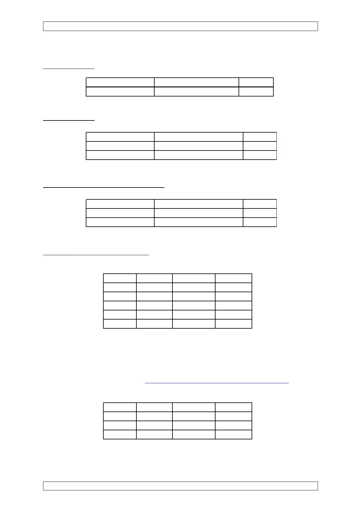
Module Slot Remark Number
MDO 1
MCP 1 1
MDA 4 1
MAI 6/8 MS 1-24 3
MGO 14 1
Module Slot Remark Number
MDA 4 1
MAI 6/8 MS 65-96 3
MGO 14 1
Calculation example of the MDA 10 module in slot 4 of rack 2:
ID calculation for:
Calculation example of the MGO 10 module in slot 14 of rack 1:
ID calculation for:
Calculation example of the MAO 10 module in slot 13 of rack 3:
ID calculation for:Configuration Example:
Configuration example:
Components of the individual racks:
Central rack
• Rack-CAN-Node Number : 1 (set on MIB-Module)
• Bit rate: 125 kB
• CAN termination at the MIB module, if CAN line to CAN bridge is < 30 cm, otherwise
provide a 120 Ohms terminating resistor at the CAN bridge, and switch off the
termination at the MIB module (see section 5.3.1 Configuration of MIB-Module).
Satellite: