REV 0, June 2005 Page 299
Operation Manual SUPREMA
12. Sensor Data Sheets
Open or Short Circuit Fault Indication:
X = Signal failure (FAIL-LED)
XX = Alarm LEDs, Signal exceeded, Signal failure (FAIL-LED)
XXX = only alarms
XXXX = Shift of Measurement value
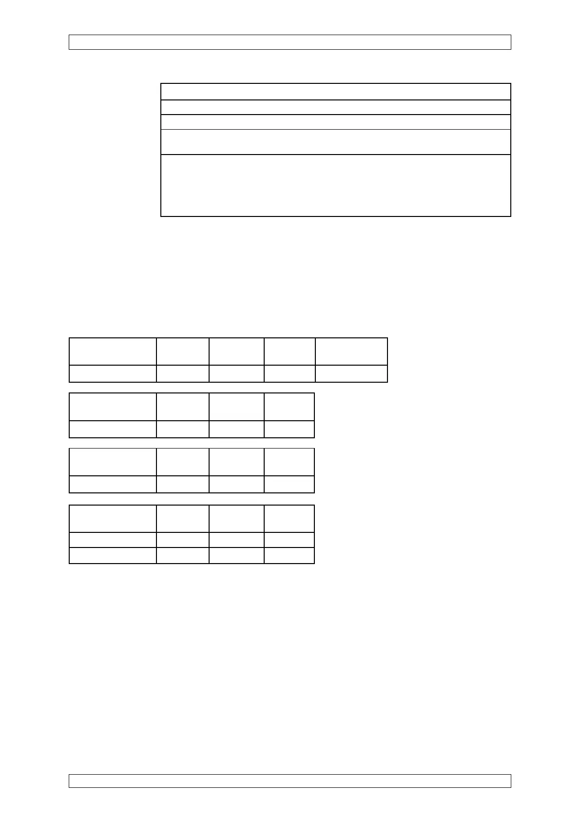
Short-circuit at the Wire Wire Wire
MAT-(TS)-Module -X1/1/-X1/2 -X1/1/-X1/4 -X1/2/-X1/4
Failure indication XX X X
Open-circuit at Wire Wire Wire
max. cable length -X1/1 -X1/2 -X1/4
Failure indication X X XX
Open-circuit at the Wire Wire Wire Disconnect plug
MAT-(TS)-Module -X1/1 -X1/2 -X1/4 of MAT-(TS)
Failure indication X X XX X
Startup: DF-8201 is consisting of VHL10 + TGS813 (S1 and S2 open)
Connection according to drawing 0756D-413 (part of the operation manual)
Warm-up period: 2 hours minimum (for operation readiness), 48 hours for calibration
Function test: Application of span gas or reference gas via test cap (Order No.: D6079762)
(0,5 l/min)
Calibration: Not using dry testgas.
Approved measuring components, calibrating conditions, measuring ranges, alarm
levels and linearisation tables see list of components:
Possible other measuring components on request.
* MCI 10
** MCI 20
Short-circuit Wire Wire Wire
max. cable length -X1/1/-X1/2 -X1/1/-X1/4 -X1/2/-X1/4
Failure indication* XX XXXX XX
Failure indication** XX X X