REV 0, June 2005 Page 303
Operation Manual SUPREMA
12. Sensor Data Sheets
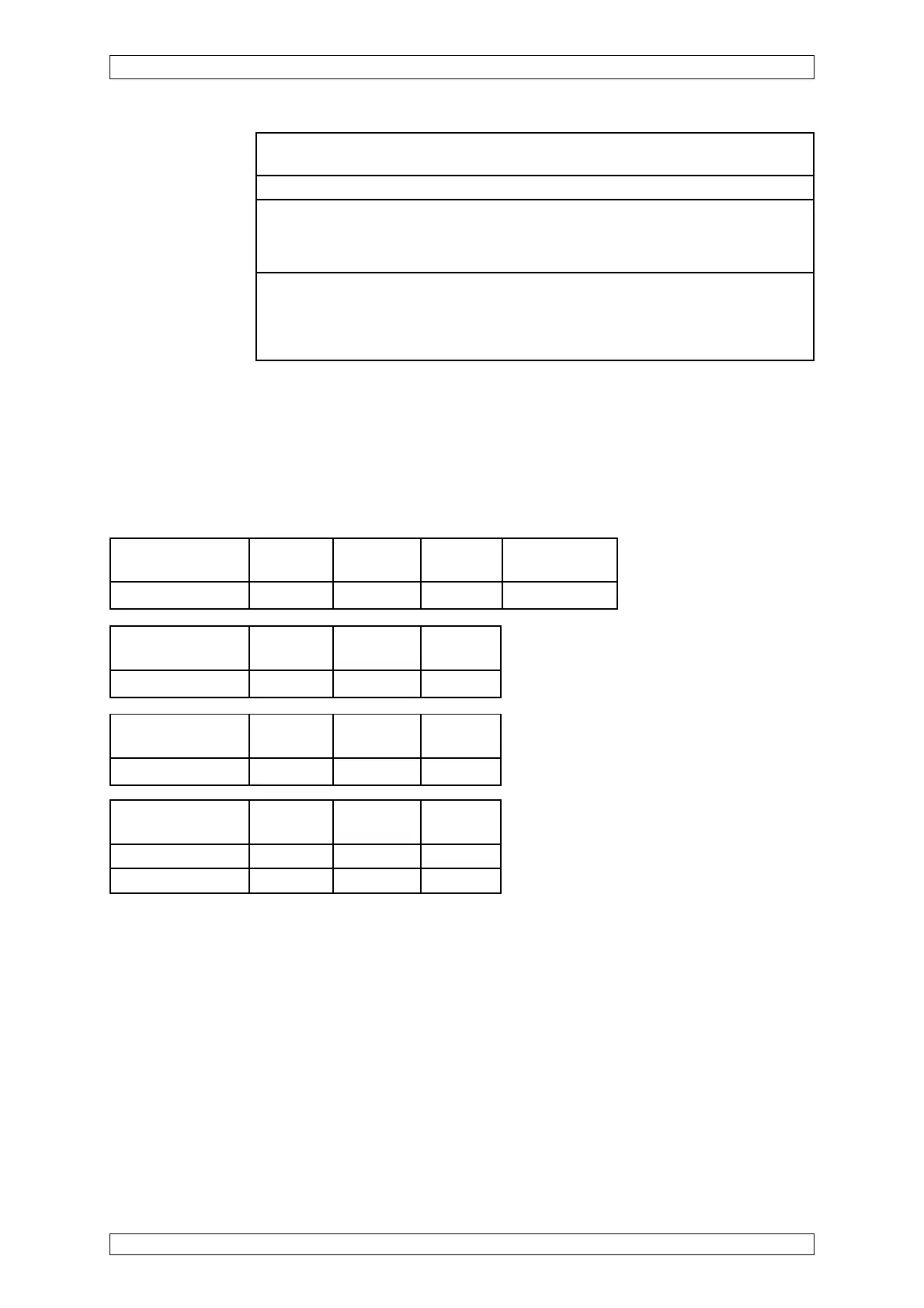
Short-circuit at the Wire Wire Wire
MAT-(TS)-Module -X1/1/-X1/2 -X1/1/-X1/4 -X1/2/-X1/4
Failure indication XX X X (a)
Open-circuit at Wire Wire Wire
max. cable length -xX1/1 -X1/2 -X1/4
Failure indication X X XX
Open or Short Circuit Fault Indication:
X = Signal failure (FAIL-LED)
XX = Alarm LEDs, Signal exceeded, Signal failure (FAIL-LED)
XXX = only alarms
(a) – After removing the short-circuit, disconnect for a short-time wire -X1/4 or plug/MAT-(TS).
Open-circuit at the Wire Wire Wire Disconnect plug
MAT-(TS)-Module -X1/1 -X1/2 -X1/4 of MAT-(TS)
Failure indication X X XX X
Startup: After switching on the operational voltage, the measuring head is ready for operation
after approx. 15 minutes.
Warm-up period: 15 minutes minimum (for presetting), 2 hours for calibration
Function test: Span gas application via: PK10 with 1.0 l/min
or PV10 with 1.0 l/min
or splashwater-proof housing with 1 l/min
Calibration: Calibration procedure according to SUPREMA operation manual
For measuring components allowed, measuring ranges, lower alarm levels and
conditions for calibration see list of components. (Order No.: D0792420)
Possible other measuring components and measuring ranges on request.
* MCI 10
** MCI 20
Short-circuit Wire Wire Wire
max. cable length -X1/1/-X1/2 -X1/1/-X1/4 -X1/2/-X1/4
Failure indication* XX XXX XX
Failure indication** XX X X