REV 0, June 2005 Page 323
Operation Manual SUPREMA
12. Sensor Data Sheets
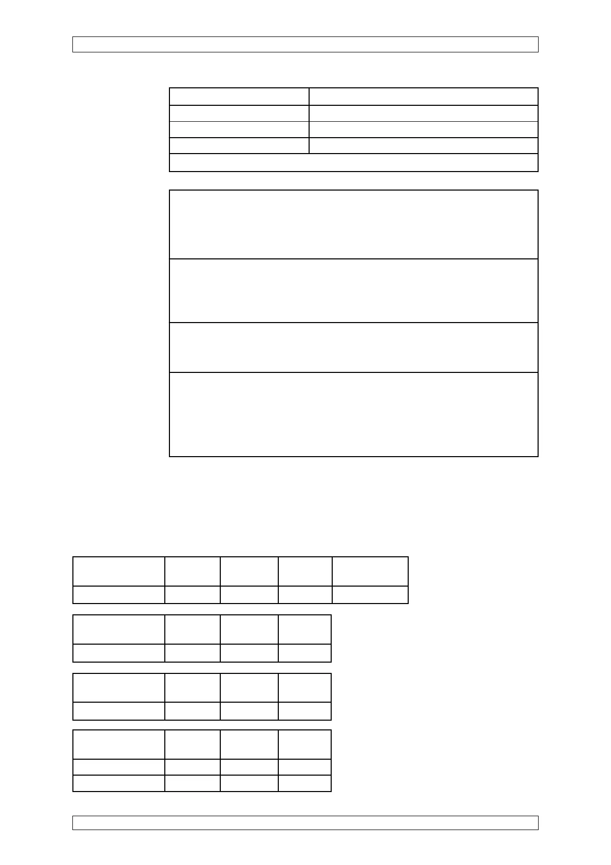
Pressure 950 ... 1100 hPa
Weight approx. 2.9 kg
Dimensions Diameter approx. 100 mm; Length approx. 250 mm
Housing material Stainless steel(ASMT 316/DIN1.4401)
For further details see operation manual. (Order No.: D0770041)
Open or Short Circuit Fault Indication:
X = Signal failure (FAIL-LED)
XX = Alarm LEDs, Signal exceeded, Signal failure (FAIL-LED)
XXX = only alarms
XXXX = INHIBIT / supressed
Short-circuit at the Wire Wire Wire
MAT-(TS)-Module -X1/1/-X1/2 -X1/1/-X1/4 -X1/2/-X1/4
Failure indication XX XXXX X
Open-circuit at Wire Wire Wire
max. cable length -X1/1 -X1/2 -X1/4
Failure indication X X XXXX
Open-circuit at the Wire Wire Wire Disconnect plug
MAT-(TS)-Module -X1/1 -X1/2 -X1/4 of MAT-(TS)
Failure indication X X XXXX X
Startup: After switching on the supply voltage, the instrument initiates a self-test.
Ia = 0 mA; —> After approx. 60 sec. the instrument changes over to measuring
operation. Ia = 4 mA (Zero)
Explosion range: Before opening the terminal compartment, power to the measuring
head must be switched off.
Status signals: If the optics is contaminated more than 70 % —> Ia is reaching 1 mA
Indication at the SUPREMA display: Signal failure
Sensor failure (failure of electronics or measuring path break) —> Ia reaches 0 mA
Indication at the SUPREMA display: Signal failure
Function test: Span gas application via gas inlet piece:
Weather protection housing —> 4.0 l/min (at approx. 0 m/s wind speed)
Flow cell —> approx. 1.0 l/min (independent from the wind velocity)
Calibration: New calibrations or calibration changes can only be made by MSA AUER service
personnel or by specialists authorized by MSA AUER.
For approved measuring components, calibrating conditions, measuring ranges, alarm
levels and linearisation tables see list of components (Order No.: D0770405) or
appendix 2 of the operation manual
Possible other measuring components on request.
* MCI 10
** MCI 20
Short-circuit Wire Wire Wire
max. cable length -X1/1/-X1/2 -X1/1/-X1/4 -X1/2/-X1/4
Failure indication* XX XX X
Failure indication** XX X X