REV 0, June 2005 Page 329
Operation Manual SUPREMA
12. Sensor Data Sheets
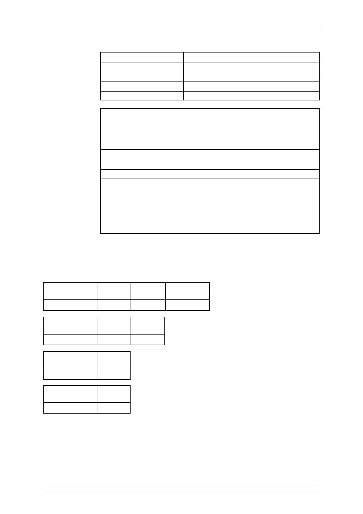
Short-circuit at Wire
max. cable length -X1/1/-X1/4
Failure indication X
Short-circuit at the Wire
MAT-(TS)-Module -X1/1/-X1/4
Failure indication X
Open-circuit at Wire Wire
max. cable length -X1/1 -X1/4
Failure indication X X
Open or Short Circuit Fault Indication:
X = Signal failure (FAIL-LED)
XX = Alarm LEDs, Signal exceeded, Signal failure (FAIL-LED)
Open-circuit at the Wire Wire Disconnect plug
MAT-(TS)-Module -X1/1 -X1/4 of MAT-(TS)
Failure indication X X X
Startup: After switching on the supply voltage, the instrument initiales a self-test.
Ia = 3 mA (adjustable); —> After 5 minutes, the instrument changes over to measuring
operation. Ia = 4 mA
Explosion range: Before opening the terminal compartment, power to the measuring
head must be switched off.
Status signals: Calibration —> 3 mA ; Failure —> 2 mA: Cable defect —> 0 mA
Indication at the SUPREMA display: Signal failure
Function test: IR test filter
Calibration: Calibration demand of SUPREMA measuring points —> (INHIBIT/ alarm suppression)
current output in calibration mode —> 3 mA
After confirmation, changeover to measuring operation.
For approved measuring components, calibrating conditions, measuring ranges, alarm
levels and linearisation tables see list of components. (Order No.: 0770406)
Possible other measuring components on request.
Pressure 950 ... 1100 hPa
Weight detector approx. 3.9 kg
Weight source approx. 4.9 kg
Dimensions W x D x H (detec.) 132 mm x 115 mm x 132 mm
Dimensions W x D x H (source) 132 mm x 115 mm x 132 mm