REV 0, June 2005 Page 333
Operation Manual SUPREMA
12. Sensor Data Sheets
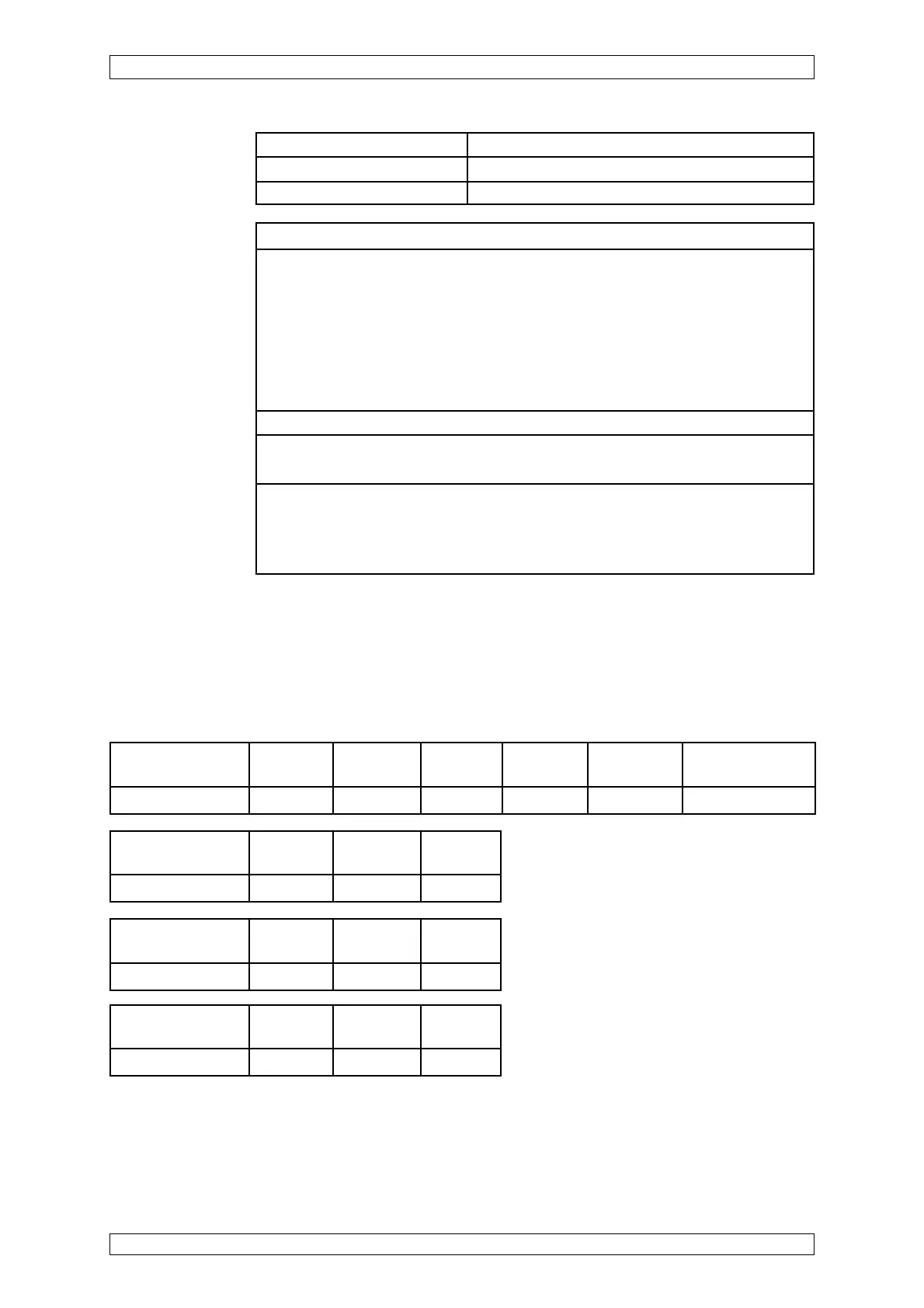
Open or Short Circuit Fault Indication:
X = Signal failure (FAIL-LED)
XX = Alarm LEDs, Signal exceeded, Signal failure (FAIL-LED)
XXX = only alarms
XXXX = no change of indication
Short-circuit at Wire Wire Wire
max. cable length -X1/2/-X1/3 -X1/2/-X1/4 -X1/3/-X1/4
Failure indication XX XXXX X
Short-circuit at the Wire Wire Wire
MAT-(TS)-Module -X1/2/-X1/3 -X1/2/-X1/4 -X1/3/-X1/4
Failure indication XX X X
Open-circuit at Wire Wire Wire
max. cable length -X1/2 -X1/3 -X1/4
Failure indication X X X
Open-circuit at the Wire Wire Wire Bridge Bridge Disconnect plug
MAT-(TS)-Module -X1/2 -X1/3 -X1/4 -X1/1/-X1/2 -X1/4/-X1/5 of MAT-(TS)
Failure indication X X X XX X X
Startup: Presetting required —> before first calibration and when changing sensor
Presetting: Connect digital voltmeter to MAI card jacks.
Bridge current setting —> 310 mA for all measuring components
Zero adjustment by zero gas —> Zero setting to Ua = 400 ... 450 mV
Sensitivity adjustment with measuring gas —> Measuring range level
Ua = 1950 ... 2100 mV
or by means of the value of the existing gas concentration according to:
Ua (mV) = C (Span gas concentration in % of measuring range) / 100
*
1600 + 400
Warm-up period: 15 minutes minimum for presetting, 2 hours for calibration
Function test: Span gas application via: Test cap (Calibration Adaptor Assembly)
0,25 l/min
Calibration: Calibration procedure according to SUPREMA operation manual
For measuring components allowed, measuring ranges, lower alarm levels and
conditions for calibration see list of components.
Possible other measuring components and measuring ranges on request.
Pressure 950 ... 1100 hPa
Weight approx. 1.2 kg
Dimensions W x D x H 120 mm x 72 mm x 140 mm