REV 0, June 2005 Page 345
Operation Manual SUPREMA
12. Sensor Data Sheets
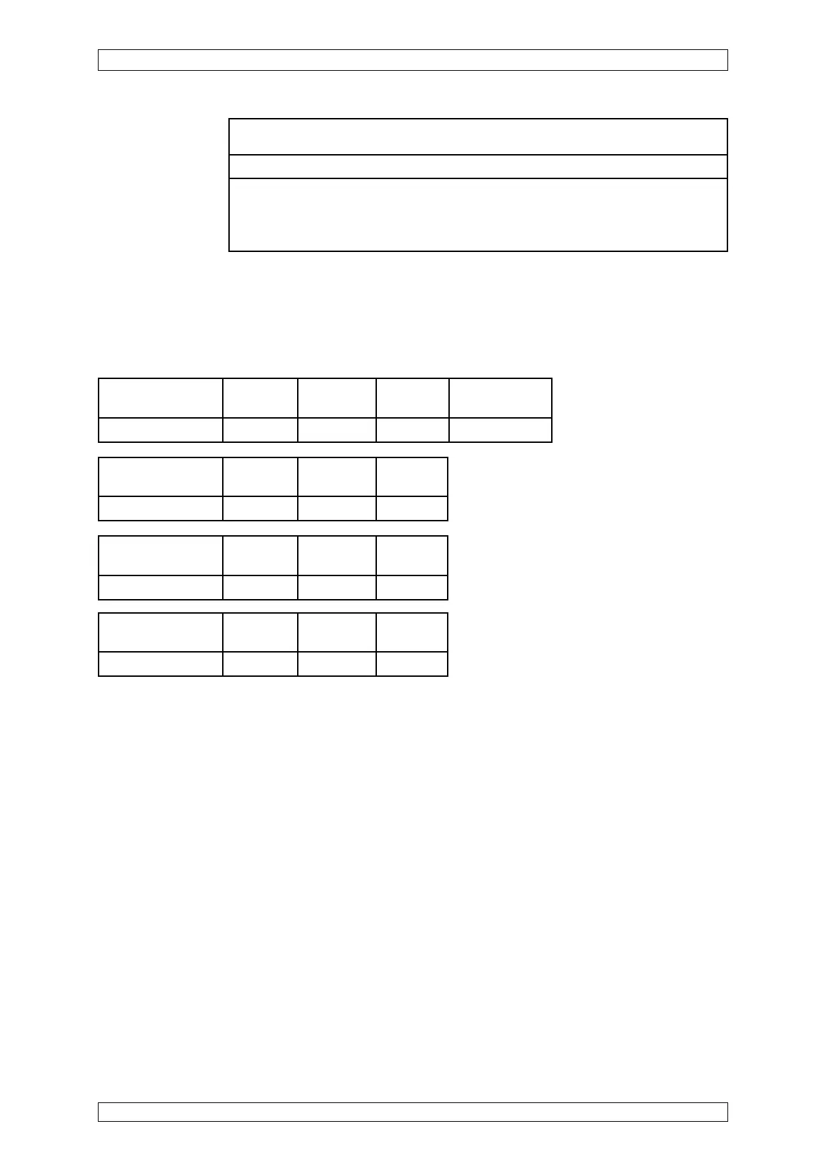
Open or Short Circuit Fault Indication:
X = Signal failure (FAIL-LED)
XX = Alarm LEDs, Signal exceeded, Signal failure (FAIL-LED)
XXX = only alarms
Short-circuit at the Wire Wire Wire
MAT-(TS)-Module -X1/1/-X1/2 -X1/1/-X1/4 -X1/2/-X1/4
Failure indication XX X X
Open-circuit at Wire Wire Wire
max. cable length -X1/1 -X1/2 -X1/4
Failure indication X X X
Open-circuit at the Wire Wire Wire Disconnect plug
MAT-(TS)-Module -X1/1 -X1/2 -X1/4 of MAT-(TS)
Failure indication X X X X
Short-circuit Wire Wire Wire
max. cable length -X1/1/-X1/2 -X1/1/-X1/4 -X1/2/-X1/4
Failure indication XX XXX X
Startup: After switching on the supply voltage the instrument initiates a self-test. After
approximately 30 sec. the instrument changes over to measuring operation.
Function test: Span gas via UltimaX IR test cap
Calibration: New calibrations or calibration changes can only be made by MSA AUER service
personnel or by specialists authorized by MSA AUER. For allowed measuring
ranges, lower alarm levels and conditions for calibration see list of gases:
Possible other measuring components on request.