7
RFL Electronics Inc. June 10, 2002
RFL 9300DCDR
RFL Electronics APRIL (t) Remote Communications, Version 2.1© 1993, 1996
SUBSTATION 12
H - Display the main menu
A - Go to the alarms display
V - Go to the values display
P - Go to the programming menu (password required)
D - Go to the read settings menu
F - Go to the configuration and software version display
K - Go to the Remote Parameters display
U - Enter the update mode
X - Exit the update mode
S - Go to sequence-of-events menu
9300>_
Figure 11. APRIL commands for use with RFL 9300 (for two-terminal and three-terminal mode)
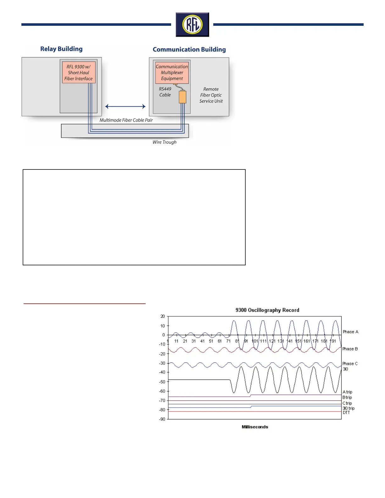
The oscillography board is an extension of the
display controller. It is directly connected to
the display controller through an 8-bit bi-direc-
tional data bus and additional control lines.
When a trip event occurs, the oscillography
board will record and store 12 cycles of all four
measured currents as well as the trip output
signals. Six cycles of pre-trip and six cycles of
post trip information will be saved.
The four current signals are read by an 8-bit ana-
log-to-digital converter and kept in a rolling buffer
by the controller. In the event of a trip, the buffer
is time tagged and a new buffer will be opened.
Five buffers are available to store oscillography
data for five of the most recent events. Oscillog-
raphy is displayed on a pc using an external
spread sheet such as MS Excel.
Oscillography
Figure 12. RFL 9300 Oscillography Record.
Figure 10. Typical RFL 9300 Short Haul Fiber Optic Application