8.25
Date Code 20171006 Instruction Manual SEL-400 Series Relays
Monitoring
Station DC Battery System Monitor
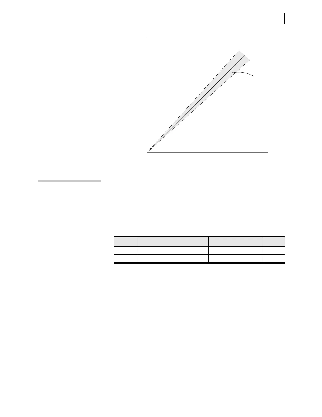
NOTE: Only the upper ground
detection factor in
Figure 8.12
is
entered as a setting. The relay
calculates the lower factor by taking
the reciprocal of the upper factor:
1/1.05 = 0.952 in this case.
If the ground detection factor ratio exceeds a setting threshold, the relay asserts
the DCIG Relay Word bit. To set the ground detection factor threshold, enable the
advanced Global settings (set EGADVS := Y), and set the DC1GF and the
DC2GF thresholds at a value close to 1.05 (the factory-default setting) to allow
for some slight battery system unbalance of around 5 percent. Table 8.11 lists the
ground detection factor threshold settings for this example.
DC Battery Monitor Alarm
You can use the battery monitor Relay Word bits to alert operators for out-of-tol-
erance conditions in the battery systems. Add the appropriate Relay Word bit to
the SEL
OGIC control equation that drives the relay control output you have
selected for alarms. For example, use the Form B contact of control output
OUT214. Set the SEL
OGIC control equation to include the battery monitor
thresholds.
OUT214 := NOT (HALARM OR SALARM OR DC1F OR DC1W OR
DC1R OR DC1G) (Output SEL
OGIC Equation)
This is one method; you can implement many other methods as well.
Figure 8.13 Ground Detection Factor Areas
|Vdc
ositive|
volts
|Vdc ne
ative|
volts
Rela
Word bit
D
1
l
rm
r
Rela
Word bit
D
1
l
rm
r
Normal o
eratin
are
k = 1.05
k = 1.00
k = 0.95
D
1
F
= 1
Table 8.11 Example DC Battery Monitor Settings—Ground Detection Factor
(EGADVS := Y)
Setting Description Indication Value
DC1GF Ground detection factor, Mon. 1 Battery wiring ground(s) 1.05
DC2GF Ground detection factor, Mon. 2 Battery wiring ground(s) 1.05