10.28
SEL-400 Series Relays Instruction Manual Date Code 20171006
Testing, Troubleshooting, and Maintenance
Maintenance
c. If the keys inside the I/O interface board receptacles are not in the
positions indicated in Figure 10.17, grasp the key edge with
long-nosed pliers to remove the key and reinsert the key in the
correct position.
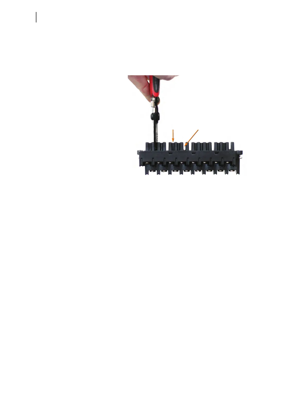
d. Break the webs of the screw-terminal connectors in the position
that matches the receptacle key, as shown in Figure 10.18.
Step 12. Attach the screw-terminal connector.
a. Mount the screw-terminal connectors to the rear panel of the
relay.
b. Tighten the screw-terminal connector mounting screws to
between 7 in-lb and 12 in-lb (0.8 Nm to 1.4 Nm).
Step 13. Reconnect the power, the interface board, and the analog input board
cables to the relay main board.
Step 14. Reconnect the cables removed in Step 6–Step 8 and reinstall the relay
front-panel cover.
Step 15. Apply power.
Step 16. Reconnect any serial cables that you removed from the communica-
tions ports in the disassembly process.
Step 17. Establish a terminal emulation session with the relay using QuickSet
SEL-5030 Software or other terminal emulation program.
Step 18. Using the terminal emulation program, enter Access Level 2.
Step 19. From Access Level 2, issue the STA command, and answer Y
<Enter> if prompted to accept the new hardware configuration.
(Note: If the I/O board was replaced with exactly the same board,
you will not be prompted to accept new hardware.)
Figure 10.18 Screw-Terminal Connector With Webs