5.35
Date Code 20171006 Instruction Manual SEL-400 Series Relays
Control
Bay Control Example Application
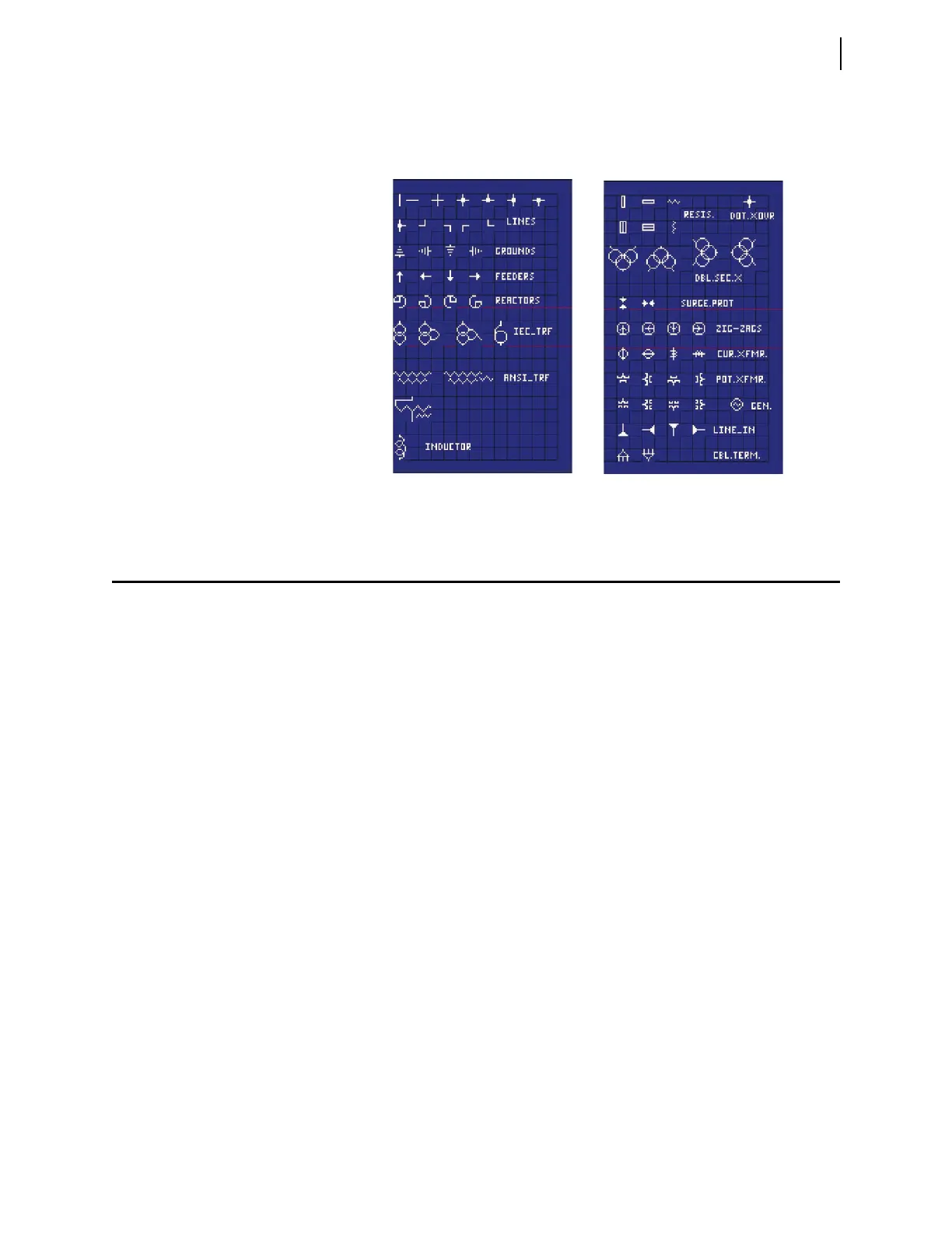
Available Power System Components
Figure 5.28 shows the different types of power system components available.
Bay Control Example Application
This example demonstrates configuring a bay control screen for an SEL-451.
Similar configurations can be done with other SEL-400 series relays.
Bus 1, Bus 2, and Transfer BUS Bay With Ground Switch (MIMIC := 4)
Figure 5.29 illustrates the Bus 1, Bus 2, and Transfer Bus Bay with Ground
Switch (MIMIC := 4). The Bay configuration used in this example provides five
disconnect switches, one breaker, and the ability to display as many as six Analog
Quantities. The labels and Analog Quantities shown in Figure 5.29 are all a result
of the settings entered in this example. See Table 5.6 for a complete list of Bay
settings for this application.
Figure 5.28 Power System Components