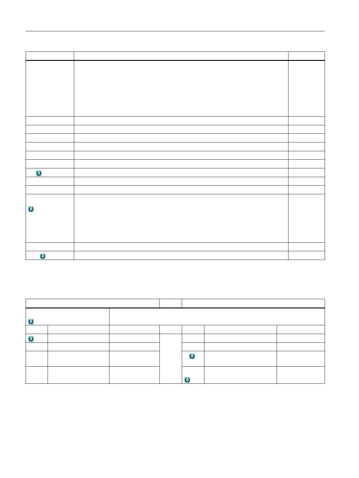
Parameter Description Unit
C0
Y0
Z0
X0
(only for Shop‐
Turn)
Peripheral surface Y: The positions refer to the reference point:
Positioning angle for machining surface – (only for single position)
Reference point Y – (only for single position)
Reference point Z – (only for single position)
Reference point X – (only for single position)
Degrees
mm
mm
mm
N Number of slots
R Radius of circumferential slot mm
α0 Starting angle Degrees
α1 Opening angle of the slot Degrees
α2 Advance angle - (for pitch circle only) Degrees
W Slot width mm
Z1 Slot depth (abs) or depth relative to Z0 or X0 (inc) - (only for ∇, ∇∇∇) mm
DZ Maximum depth infeed - (only for ∇, ∇∇∇ ) mm
UXY Plane finishing allowance – (only for ∇, ∇∇∇) mm
Positioning Positioning motion between the slots:
● Straight line:
Next position is approached linearly in rapid traverse.
● Circular:
Next position is approached along a circular path at the feedrate
defined in a machine data code.
FS Chamfer width for chamfering (inc) - (for chamfering only) mm
ZFS Insertion depth of tool tip (abs or inc) - (for chamfering only) mm
* Unit of feedrate as programmed before the cycle call
Parameters in the "Input simple" mode
G code program parameters ShopTurn program parameters
Input
● simple
Milling direction T Tool name
RP Retraction plane mm D Cutting edge number
F Feedrate * F Feedrate mm/min
mm/rev
S / V Spindle speed or constant
cutting rate
rpm
m/min
Programming technology functions (cycles)
10.4 Milling
Turning
538 Operating Manual, 06/2019, A5E44903486B AB