EasyManua.ls Logo

Spectracom SecureSync - 4]: Bottom Slot Installation

Spectracom SecureSync
599 pages
Print Icon
To Next Page IconTo Next Page
To Previous Page IconTo Previous Page
Loading...
Table 5-6:
Installation steps
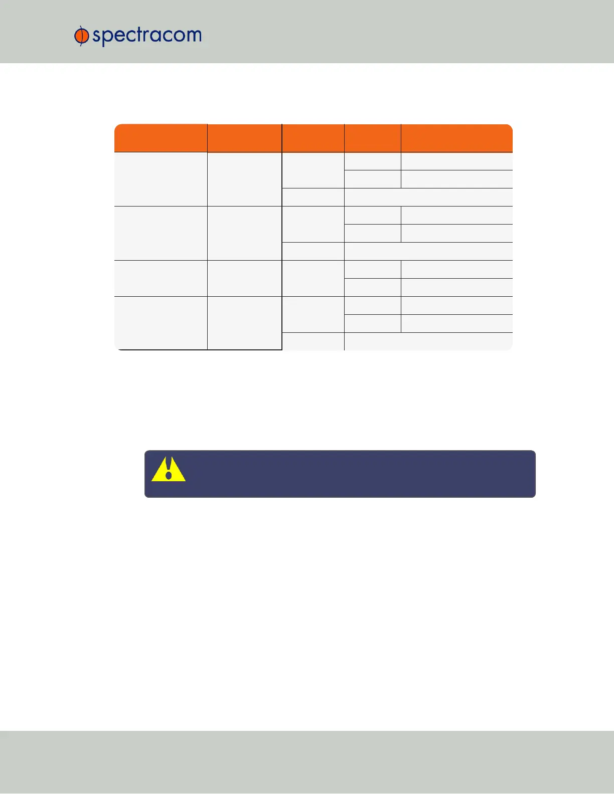
Part No. Option Card Card Function
Installation
Location
Bottom Slot PROCEDURE STEPS [x]
1204-
08
1204-
26
1204-
1C
1204-
0C
Frequency output Slot 2, 4, or 6 empty (1), 2, 3, 5, 7, 11, (12)
populated (1), 2, 3, 6, 7, 11, (12)
Slot 1, 3, or 5 (1), 2, 3, 4, 7, 11, (12)
1204-
0F
Alarm relay Slot 2, 4, or 6 empty (1), 2, 3, 5, 7, 10, 11, (12)
populated (1), 2, 3, 6, 7, 10, 11, (12)
Slot 1, 3, or 5 (1), 2, 3, 4, 7, 10, 11, (12)
1204-
06
Gigabit Ethernet Slot 2 empty (1), 2, 3, 8, 11, (12)
populated (1), 2, 3, 9, 11, (12)
All other Part No.'s (miscellaneous) Slot 2, 4, or 6 empty (1), 2, 3, 5, 11, (12)
populated (1), 2, 3, 6, 11, (12)
Slot 1, 3, or 5 (1), 2, 3, 4, 11, (12)
5.2.2.7 [4]: Bottom Slot Installation
Instructions for installing an option card into one of the three bottom slots (1, 3, or 5):
a.
Safely power down the SecureSync unit and remove the top cover of the main chassis
(housing). Save the screws.
Caution: NEVER install an option card from the rear of the unit, ALWAYS
from the top, after removing the chassis cover.
b.
Remove the blank option card plate, or the existing option card in the slot. Save the
screws. If a card is populating the slot above the bottom slot your option card is to be
installed into, remove it temporarily.
c.
Insert the card into the bottom slot by carefully pressing its connector into the mainboard
connector (see Figurebelow), and by lining up the screw holes on the card with the
chassis.
SecureSync User Reference Guide 355
APPENDIX

Table of Contents

Related product manuals