1PPS Validity: Indicates “OK” (green) if the 1PPS input signal is present and valid. Indic-
ates “Not Valid” (orange) if the 1PPS input signal is either not present or is not con-
sidered valid.
Edge: Displays the selected Edge (rising of falling) of the 1PPS input that defines the on-
time point.
Offset: Displays the configured 1PPS offset values.
The 1PPS Input signal is analyzed and an absence of the signal triggers a “Not Valid” indic-
ation.
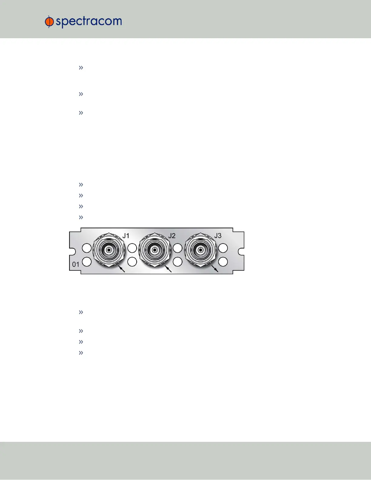
5.2.3.3 1PPS In/Out, 10MHz In [1204-01, -03]
Model 1204-01, 1PPS/Freq Input (TTL): General Specifications
Inputs/Outputs: One Frequency Input (=J1), one 1PPS Input (=J2), one 1PPS Output
Signal Type And Connector: TTL/Sine (BNC into 50 Ω)
Maximum Number of Cards: 6
Ordering Information: 1204-01: 1PPS/Freq input (TTL levels) module
Figure 5-21: Model 1204-01 option card rear plate
Model 1204-03, 1PPS/Freq Input (RS-485): General Specifications
Inputs/Outputs: (1) 1PPS Input, (1) Freq Input (1) 1PPS Output. All input and output sig-
nals are RS-485 compatible.
Signal Type And Connector: Balanced RS-485 (3.8 mm terminal block)
Maximum Number of Cards: 6
Ordering Information: 1204-03: 1PPS/Freq input (RS-485 levels) module
SecureSync User Reference Guide 377
APPENDIX