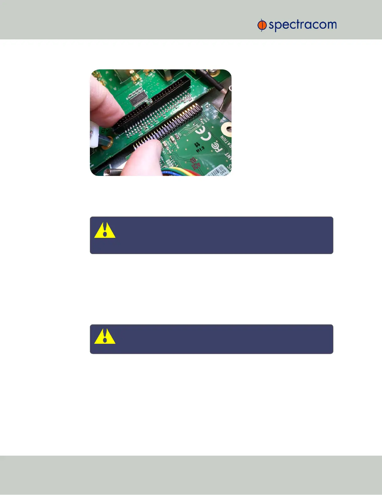
Figure 5-3: Connector installation
d.
Using the supplied M3 screws, screw the board, and the option card plate into the
chassis, applying a torque of 0.9Nm/8.9in-lbs.
Caution: Ensure that screw holes on the card are properly lined up and
secured to the chassis before powering the unit up, otherwise damage to
the equipment may result.
5.2.2.8 [5]: Top Slot Installation, Bottom Slot Empty
Instructions for installing an option card into an upper slot (2, 4, or 6) of the SecureSync unit,
with no card populating the bottom slot:
a.
Safely power down your SecureSync unit and remove the top cover of the main chassis
(housing). Save the screws.
Caution: NEVER install an option card from the rear of the unit, ALWAYS
from the top, after removing the chassis cover.
b.
Remove blank option card plate, or existing option card. Save the screws.
c.
Place one of the supplied washers over each of the two chassis screw holes (see
Figurebelow), then screw the 18mm standoffs (= the longer standoffs) into the chassis
(see Figurebelow), applying a torque of 0.9Nm/8.9in-lbs.
356 SecureSync User Reference Guide
APPENDIX