Pin A goes to the most negative voltage of the DC source. For +12V or +24/48V this would be
the ground or return output from the DC source. For a -12V or -24/48V
DC
source this would
be the negative output from the DC source.
Pin C goes to the Earth ground of the DC source.
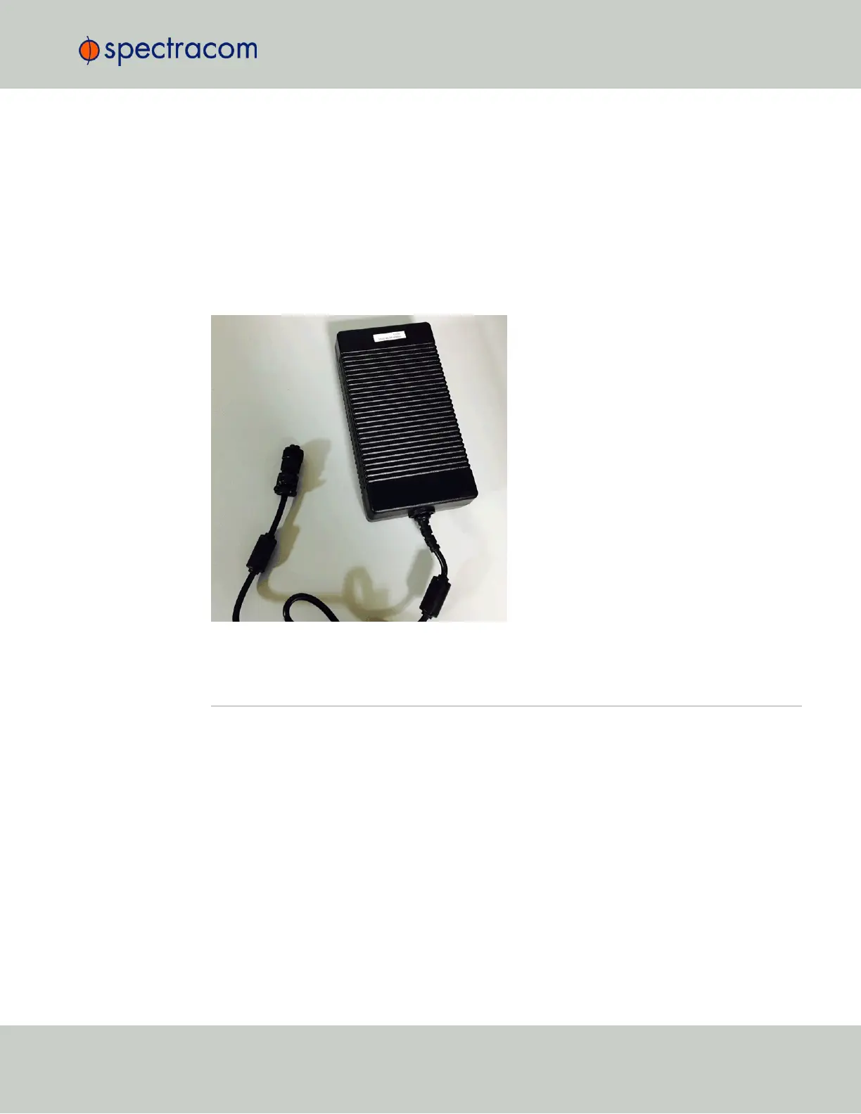
AC/DC Converter
The DC input can be used as a second AC input: As an option, Spectracom offers a kit con-
taining an AC/DC converter with a pre-assempled DC connector: The part number for this
adaptor kit is PS06R-2Z1M-DT01.
2.7 Connecting the GNSS Input
Typical installations include GNSS as an external reference input. If the GNSS receiver is not
installed or if the GNSS will not be used as a SecureSync reference, disregard the steps to
install the GNSS antenna and associated cabling.
1.
Install the GNSS antenna, surge suppressor, antenna cabling, and GNSS preamplifier
(if required). Refer to the documentation included with the GNSS antenna for additional
information regarding GNSS antenna installation.
2.
Connect the GNSS cable to the rear panel antenna input jack (see illustration under
"Unit Rear Panel" on page7).
In the event that NO antenna is connected to the rear panel jack, SecureSync will—once
it gets powered up (see "Powering Up the Unit" on page236)—activate the Antenna
Problem alarm, causing the front panel “Fault” light to be blinking orange (the Antenna
Problem alarm indicates an open or short exists in the antenna cable.)
Unless there is an open or short in the antenna cable, the "Fault" light should stop
2.7 Connecting the GNSS Input
CHAPTER 2 • SecureSync User Reference Guide Rev. 26
41