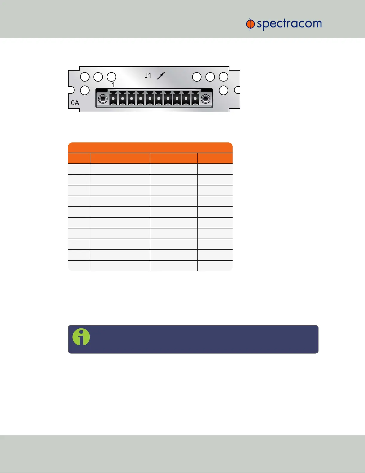
Figure 5-36: Model 1204-0A option card rear plate
Table 5-15: 1204-0A option card
pin assignments
Pin Assignments
Pin No. Signal Function Description
1 GND Ground Ground
2 1.544MHz/2.048MHz RS-485 A Terminal Square wave
3 1.544MHz/2.048MHz RS-485 B Terminal Square wave
4 GND Ground Ground
5 T1/E1 output A1 GR-499/G.703 Tip
6 T1/E1 output B1 GR-499/G.703 Ring
7 GND Ground Ground
8 T1/E1 output A2 GR-499/G.703 Tip
9 T1/E1 output B2 GR-499/G.703 Ring
10 GND Ground Ground
E1/T1 Output: Edit Window
To configure an E1/T1 data output (1.544/2.048MHz clock on J1 BNC connector and unbal-
anced E1/T1 outputs on J2 to J3 BNC connectors, or all terminal block J1 outputs), navigate to
its Edit window. For instructions, see: "Configuring Option Card Inputs/Outputs" on page348.
In the Web UI this card is listed under: E1/T1 Out BNC and E1/T1 OUT Terminal.
Note: SecureSync starts numbering I/O ports with 0 (only 1PPS and 10MHz out-
puts start at1, because of the built-in outputs).
406 SecureSync User Reference Guide
APPENDIX