Pin Num-
ber
Signal Function Notes
3 SERIAL_IN_
RX
RS-232 Receive
data
Data input into unit; use this to transmit commands
to the unit)
4 NC No connection
5 GND Ground
Bottom row of 4 pins
6 NC No connection
7 NC No connection
8 NC No connection
9 NC No connection
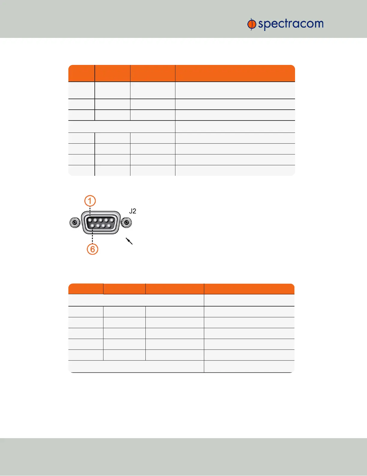
Pin Assignments: INPUT connector J2
Figure 5-51: INPUT connector J2
Table 5-22:
Pin-out, INPUT connector "J2"
Pin Number Signal Function Notes
Top row of 5 pins
1 PPS_IN 1PPS input
2 SERIAL_IN_RX RS-232 Receive data Data input into unit; ToD message
3 NC No Connection
4 NC No connection
5 GND Ground
Bottom row of 4 pins
458 SecureSync User Reference Guide
APPENDIX