Universal synchronous asynchronous receiver transmitter (USART) UM0306
410/519
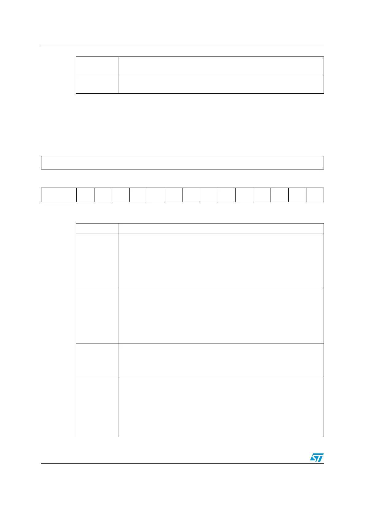
17.4.4 Control register 1 (USART_CR1)
Address Offset: 0Ch
Reset Value: 0000h
Bits 15:4
DIV_Mantissa[11:0]: mantissa of DIV.
These 12 bits define the mantissa of the USART Divider (DIV)
Bits 3:0
DIV_Fraction[3:0]: fraction of DIV.
These 4 bits define the fraction of the USART Divider (DIV)
31 30 29 28 27 26 25 24 23 22 21 20 19 18 17 16
Reserved
1514131211109876543210
Reserved UE M WAKE PCE PS PEIE TXEIE TCIE
RXNE
IE
IDLEIE TE RE RWU SBK
rw rw rw rw rw rw rw rw rw rw rw rw rw rw
Bits 31:14 Reserved, forced by hardware to 0.
Bit 13
UE: USART Enable.
When this bit is cleared the USART prescalers and outputs are stopped and the
end of the current
byte transfer in order to reduce power consumption. This bit is set and cleared by
software.
0: USART prescaler and outputs disabled
1: USART enabled
Bit 12
M: word length.
This bit determines the word length. It is set or cleared by software.
0: 1 Start bit, 8 Data bits, n Stop bit
1: 1 Start bit, 9 Data bits, 1 Stop bit
Note:
The M bit must not be modified during a data transfer (both transmission and
reception)
Bit 11
WAKE: Wake-up method.
This bit determines the USART Wake-Up method, it is set or cleared by software.
0: Idle Line
1: Address Mark
Bit 10
PCE: Parity Control Enable.
This bit selects the hardware parity control (generation and detection). When the
parity control is enabled, the computed parity is inserted at the MSB position (9th
bit if M=1; 8th bit if M=0) and parity is checked on the received data. This bit is set
and cleared by software. Once it is set, PCE is active after the current byte (in
reception and in transmission).
0: Parity control disabled
1: Parity control enabled
 Loading...


