6 Robot Settings
6.4 Zones
6-28
HW1485509
HW1485509
5. Select {Cubic} from the pull-down list at Type.
6. Select the desired Action from the pull-down list.
7. Select the Reference Coordinates from the pull-down list.
– World: Currently, it is same as the Robot
– Robot: This zone is referred to the Robot frame when it is created
– User: This zone is referred to the user frame when it is created
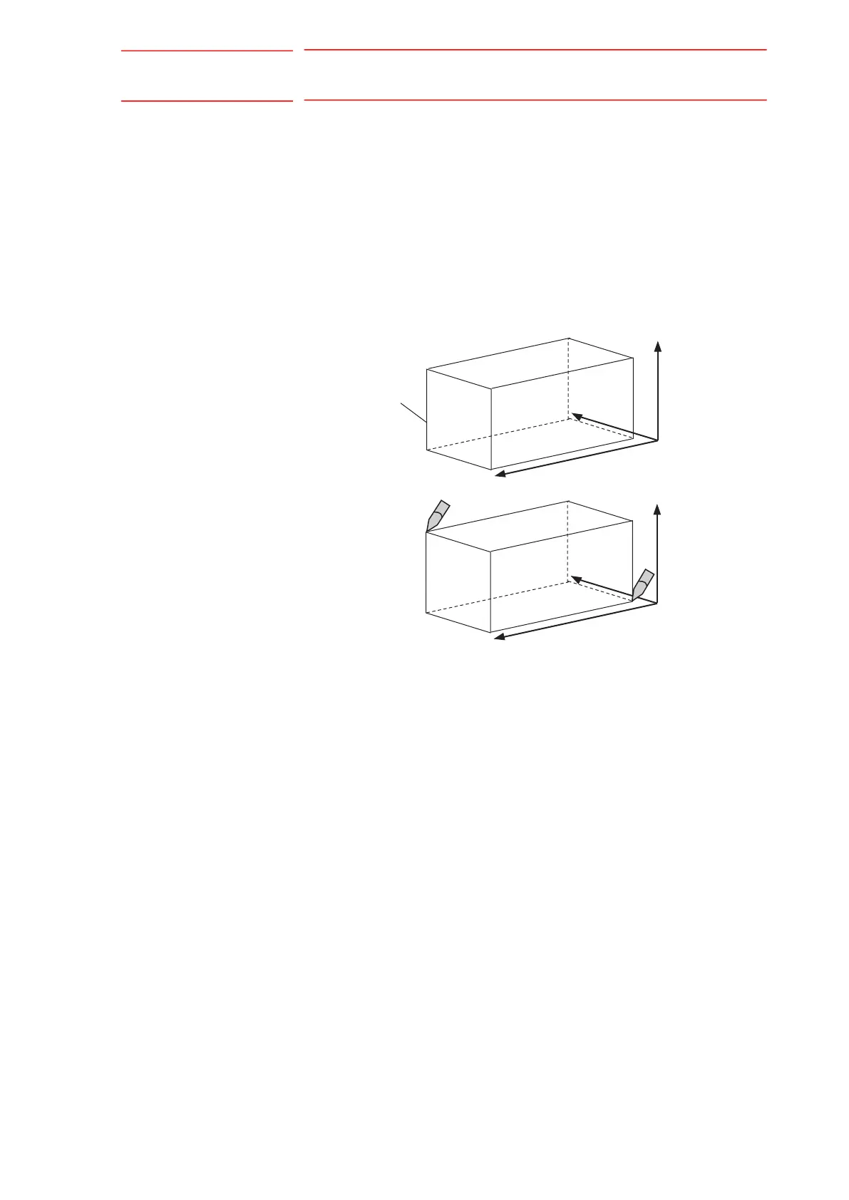
8. Enter the minimum (Corner 1) values of X, Y, Z either 1) by moving the
manipulator to the corner or 2) by manually entering the data.
To move the manipulator via the touch screen, press {Robot Jog Panel} on
the bottom of the screen to display the touch buttons.
9. Press {SET CORNER 1}
The position of the corner can be checked visually by pressing {GO TO
CORNER 1} after it is set.
10. Enter the maximum (Corner 2) values of X, Y, Z by either moving the
manipulator to the corner or by manually entering the data.
To move the manipulator from the touch screen, press {Robot Jog
Panel} on the bottom of the screen to open the touch buttons.
11. Press {SET CORNER 2}
The position of the corner can be checked visually by pressing {GO TO
CORNER 2} after it is set.
12. In the case of a Zone with “User” Reference Coordinate, the correct
User Frame must also be set. Select {User Frame #} and select the
proper User Frame from the list.
Minimum
value
X-axis
Y-axis
Z-axis
Maximum
value
Zone
Minimum
value
X-axis
Y-axis
Z-axis
Maximum
value