EasyManua.ls Logo

Emotron VS10 - Page 422

Emotron VS10
528 pages
Print Icon
To Next Page IconTo Next Page
To Previous Page IconTo Previous Page
Loading...
422 01-6203-01R3, CG Drives & Automation
Example for operating mode
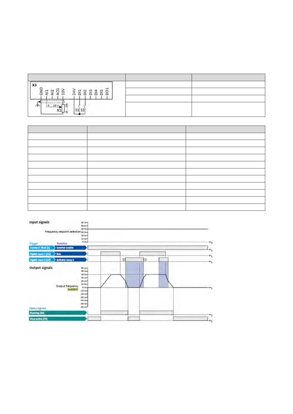
Switch S1 starts the motor in forward direction of rotation. Switch S1 in the initial
position stops the motor again.
Switch S2 activates the acceleration time 2 and deceleration time 2.
Connection plan
function
Potentiometer R1
Frequency setpoint
Switch S1 Run
Switch S2
Activate ramp 2
Parameter
Name
Setting for this example
0x2631:001 (P400.01)
Enable inverter
Constant TRUE [1]
0x2631:002 (P400.02)
Run
Digital input 1 [11]
0x2631:004 (P400.04)
Reset fault
Not connected [0]
0x2631:039 (P400.39)
Activate ramp 2
Digital input 2 [12]
0x2824 (P200.00)
Control selection
Flexible I/O configuration [0]
0x2838:003 (P203.03)
Stop method
Standard ramp [1]
0x2860:001 (P201.01)
Frequency control: Default setpoint source
Analog input 1 [2]
0x2917 (P220.00)
Acceleration time 1
10.0 s
0x2918 (P221.00)
Deceleration time 1
10.0 s
0x2919 (P222.00)
Acceleration time 2
5.0 s
0x291A (P223.00)
Deceleration time 2
5.0 s
The
status
signals can be assigned to digital outputs.
Configuration of digital outputs
429
① Change-over to deceleration time 2 during the deceleration phase.
② Change-over to acceleration time 1 during the acceleration phase.

Table of Contents

Other manuals for Emotron VS10

Related product manuals