EPSON EPL-N3000/AcuLaser M4000N Revision C
Disassembly and Assembly 150 Paper Cassette 179
Confidential
Installation
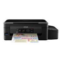
1. After inserting the hook at the front end of the RACK SIZE into the groove of the
HOUSING EXTENSION 150, turn it in the direction opposite to the arrow.
2. As shown in the figure, match the end of the RACK SIZE to the ∇ mark of the
HOUSING EXTENSION 150, and install the RACK SIZE to the HOUSING
EXTENSION 150.
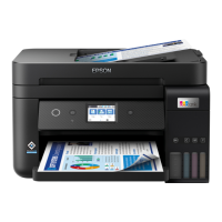
3. Install the COVER EXTENSION to the HOUSING EXTENSOR 150 with the
four screws (gold, tapping, 6mm).
4. With the LINK SW SIZE 1-150, LINK SW SIZE 2-150 and LINK SW SIZE 3-150 of the
HOUSING BASE 150 pushed to the outside as shown in the figure, assemble the
HOUSING EXTENSION 150 into the HOUSING TOP 150 and HOUSING BASE 150.
5. After securing the HOUSING TOP 150 to the HOUSING BASE 150 with the four
hooks, secure it with the two screws (gold, tapping, 8mm) in each of the left and
right sides and the six screws (gold, tapping, 8mm) in the rear side.
Figure 4- 14. RACK SIZE Installation
Figure 4- 15. RACK SIZE Installation
C A U T I O N
Before installing the RACK SIZE, pull out the GUIDE ASSY END
150 to the full (NOTE 1).
C H E C K
P O I N T
When installing it, make certain that the COVER EXTENSION is
located under the three claws of the HOUSING EXTENSION 150
(NOTE 2). (
p.178)
C A U T I O N
Always use the securing screws of 6mm length. If they are of 8mm
length, the HOUSING EXTENSION 150 will not operate smoothly
and the LOCK EXTENSION will not operate properly.
C A U T I O N
Insert the two claws at the front end of the PLATE ASSY BTM into
the hooks of the HOUSING TOP 150 (NOTE 3). (
p.177)
C H E C K
P O I N T
After completion of installation, move the GUIDE ASSY END 150
to confirm that the LINK SW SIZE operates smoothly.
RACK SIZE
GUIDE END 150
JG3009AB
NOTE 1
11)
JG3200A