10-18 Phaser 5500 Printer Service Manual
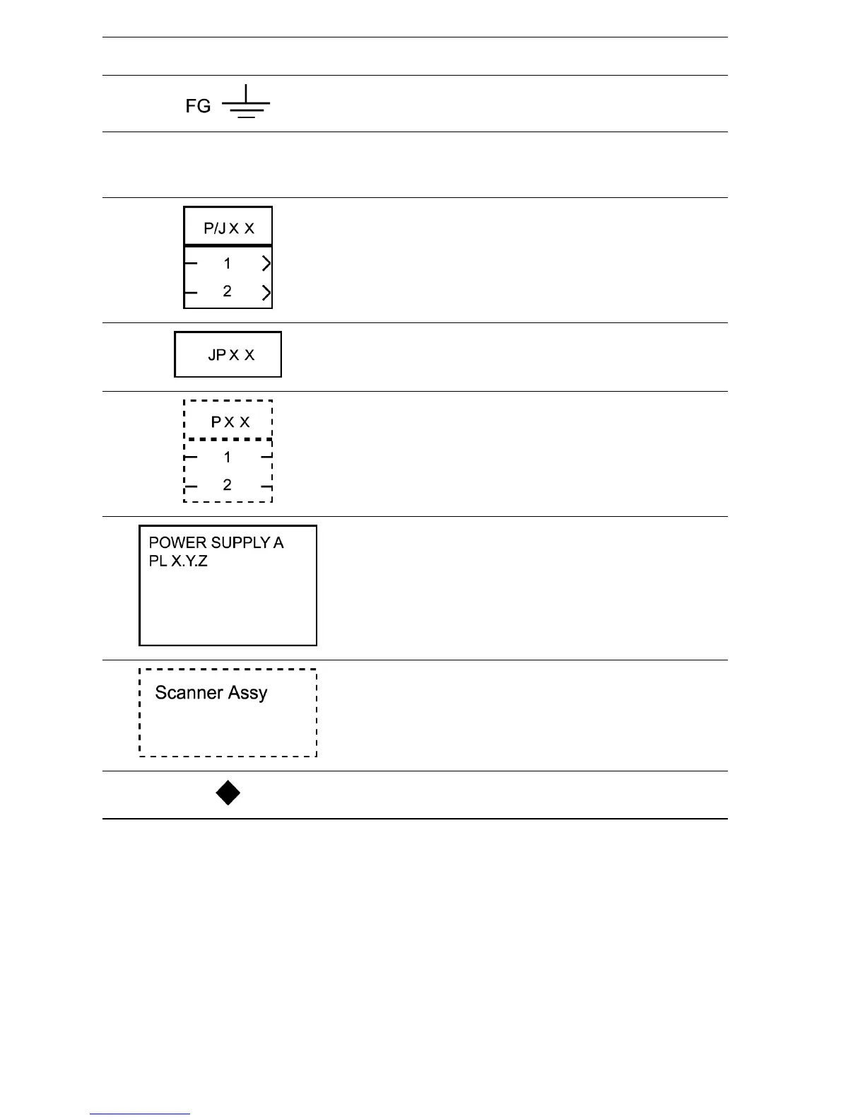
Indicates a frame ground (FG).
RTN
Indicates a return.
Represents a connector. The connector and PIN Nos.
are shown at the upper and lower parts respectively.
“P,-” indicates the plug side of the connector.
“J,>” indicates the jack side of the connector.
Represents a connection terminal with a plate spring on
the printed circuit board. The connector No. is indicated
inside the box.
Represents a connector directly connected to the
printed circuit board. The connector No. is indicated
inside the box.
Represents a part.
“PL X.Y.Z” indicates the item “Z” of the plate (PL) “X.Y”
described in Chapter 5 “Parts List”.
Represents a functional part within a part, and indicates
the name of the functional part.
Indicates a reference item associated with the section.
Symbol Description

 Loading...


