General Precautions of EFI System Maintenance
F-11
Malfunction Diagnostic Guide:
Required Equipment: (Diagnostic Instrument with EOBD Diagnostic Function, Digital Multimeter, and
Correct Circuit Diagram)
Step I: Use diagnostic instrument to read the malfunction information
Read Result I Read Result II
MIL Lamp On P-CODE Present MIL Lamp Off P-CODE Present
P0030 P0030
Maintenance tips:
The malfunction has been confirmed, and the
following problems may possibly exist
1) The circuit connected to the Pin 26# of
ECU and the Pin C# of upstream oxygen
sensor in open circuit
2) The circuit for Pin D# of upstream oxygen
sensor connected to main relay in open
circuit
3) The Pin C# and the Pin D# of upstream
oxygen sensor in open circuit
Maintenance tips:
The malfunction is not ultimately confirmed and it may
possibly be a random malfunction. Inspect the following
items:
1) Measure the electric resistance in the line between
the Pin 26# for connector of ECU and the Pin B# of
upstream oxygen sensor.
2) Measure the electric resistance from the Pin C# of
upstream oxygen sensor to the main relay.
3) Measure the electric resistance between the Pin C#
and the Pin D# of upstream oxygen sensor.
4) Inspect whether or not the contact for the connector
of oxygen sensor and the connector of ECU is under
good condition.
10. P0031 Upstream Oxygen Sensor Heating Control Circuit Short to Ground
Description about Malfunction Cause:
After engine has been started, the voltage of upstream oxygen sensor heating circuit is to be measured by the
circuit control module inside ECU, and when the voltage complies with the voltage in the mode of short to
ground, it is determined to be the heating circuit of upstream oxygen sensor short to ground.
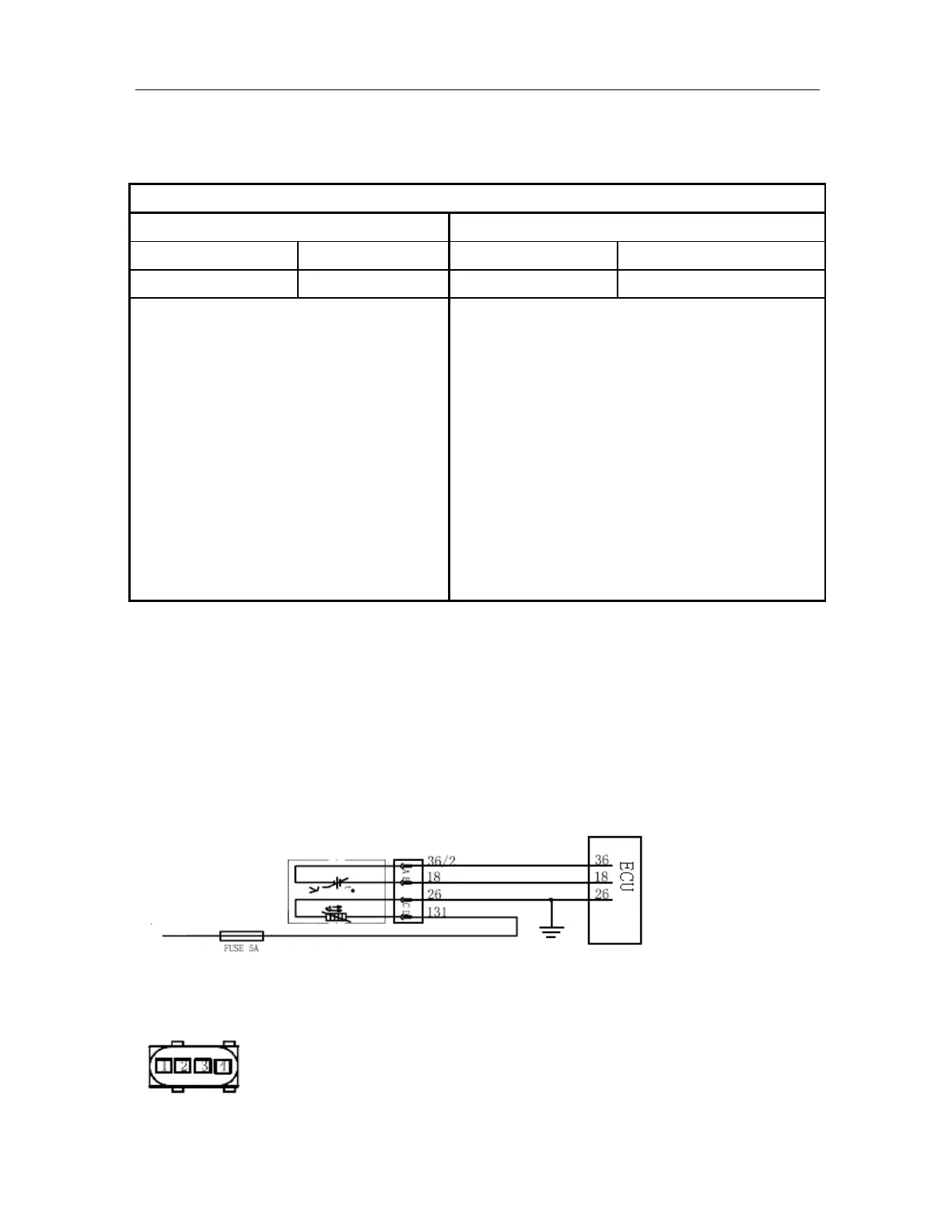
Schematic Circuit:
Main relay