Switch and relay
T-71
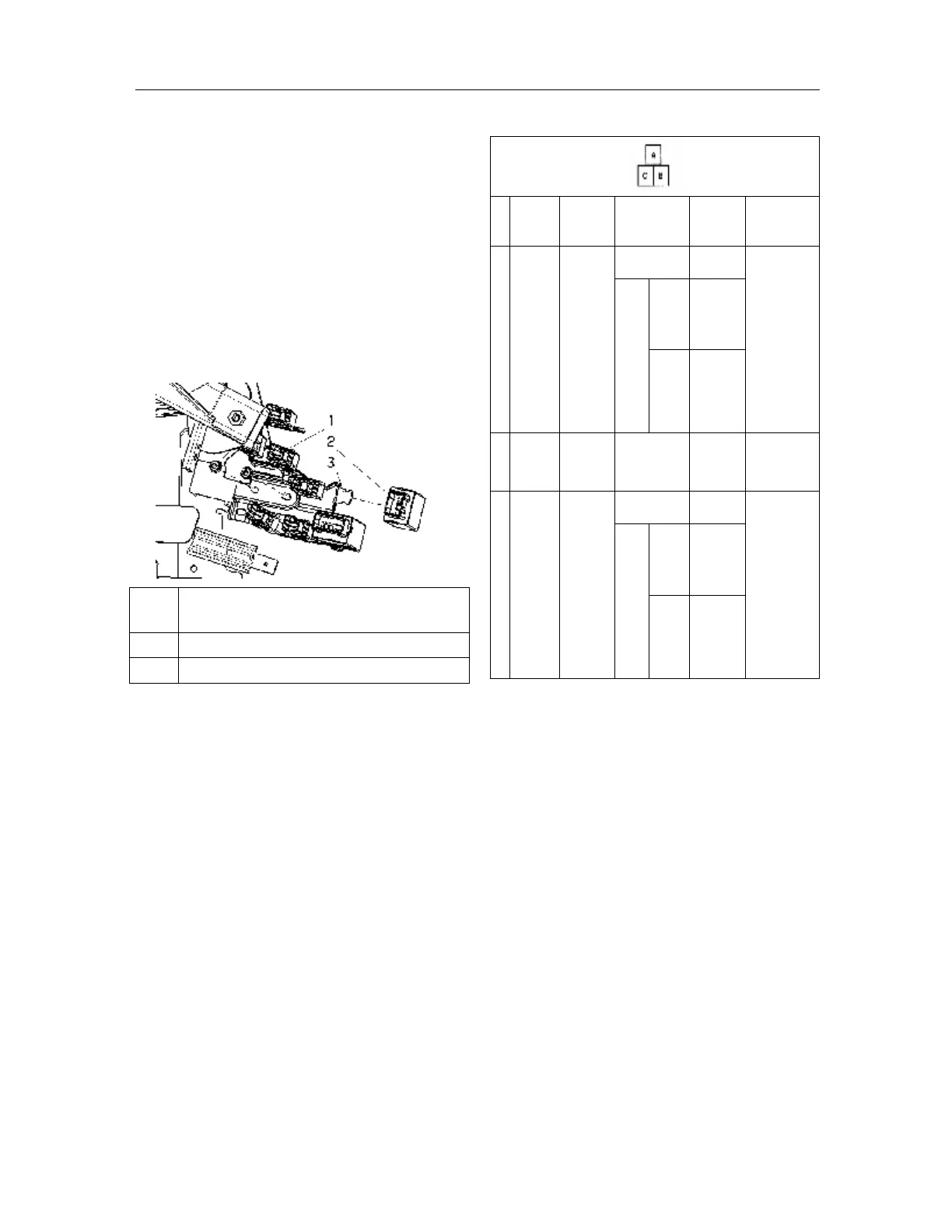
Removal/installation of flasher unit
Note: The lock part of this unit is vulnerable. If
unnecessary for replacement, do not remove it from
the bracket. Prior to the removal, be sure to check
first the flasher unit.
1. Disconnect battery negative cable;
2. Remove the bracket;
3. Disconnect the connector of flasher unit;
4. Pry up with a flathead screwdriver the upper
part of lock piece and remove the flasher unit;
5. The installation procedure is in reverse order
with that of removal.
1
Fixing nut HQ99940-0600 (torque: 7.2~12
N.m)
2 Flashing relay
3 Bracket component
Test of flasher unit
1. Remove the bracket and draw it toward
yourself;
2. Measure the terminal voltage of flasher unit as
shown in Fig.
3. Disconnect the negative cable of battery prior
to check of the continuity of terminal C.
4. If it fails to meet the technique requirements,
check all parts listed in the following table. If
the components and harnesses are normal, but
the system still works improperly, replace the
flasher unit.
Table of terminal voltage (only for reference)
B+ battery positive voltage
Removal/installation of headlamp relay
Pin
Signal
Connected
to
Testing
conditions
Voltage
(V)/
continuity
Check position
A
Flasher
unit
output
Alarm
switch
On
Change B+
and 0
l Alarm
switch
l Steering
signal
light
Alarm
Off
switch
ON
position
B +
switch
in
LOCK
state
0
B
Flasher
unit
grounding
GND
Continue:
grounding
Yes GND
C
Power
supply
Alarm
switch
Alarm switch
On
B +
l Alarm
fuse 15A
l Instrument
fuse 15A
l Alarm
switch
Alarm
switch
Off
switch
On
position
B +
switch
LOCK
state
0
1. Disconnect battery negative cable;
2. Remove the cover of main fuse box;
3. Remove the horn relay;
4. Remove as per the order indicated in the Table;
5. The installation procedure is in reverse order
with that of the removal.