General Precautions of EFI System Maintenance
F-32
36. P0170 Offline Test Air-Fuel Ratio for Self-learning under Closed-Loop Control
Irrational
Description about Malfunction Cause:
When quick diagnosis is performed for offline test using diagnostic instrument to trigger fuel self-learning
value, through about 50S, the self-learning value of mixed gas is always failed to be stabilized, hence this
malfunction is reported.
37. P0171 Offline Test Air-Fuel Ratio for Self-learning under Closed-Loop Control too
Lean
Description about Malfunction Cause:
When quick diagnosis is performed for offline test using diagnostic instrument to trigger fuel self-learning
value, the air-fuel ratio for self-learning under closed-loop control is too lean, and the self-learning value
exceeds certain threshold, hence this malfunction is reported.
38. P0172 Offline Test Air-Fuel Ratio for Self-learning under Closed-Loop Control too
Rich
Description about Malfunction Cause:
When quick diagnosis is performed for offline test using diagnostic instrument to trigger the fuel self-learning
value, the air-fuel ratio for self-learning under closed-loop control is too rich, and the self-learning value
exceeds certain threshold, hence this malfunction is reported.
Note: The 3 P-CODEs of P0170, P0171, and P0172 will be diagnosed only when KWP2000 is triggered, and
they are normally performed during offline test.
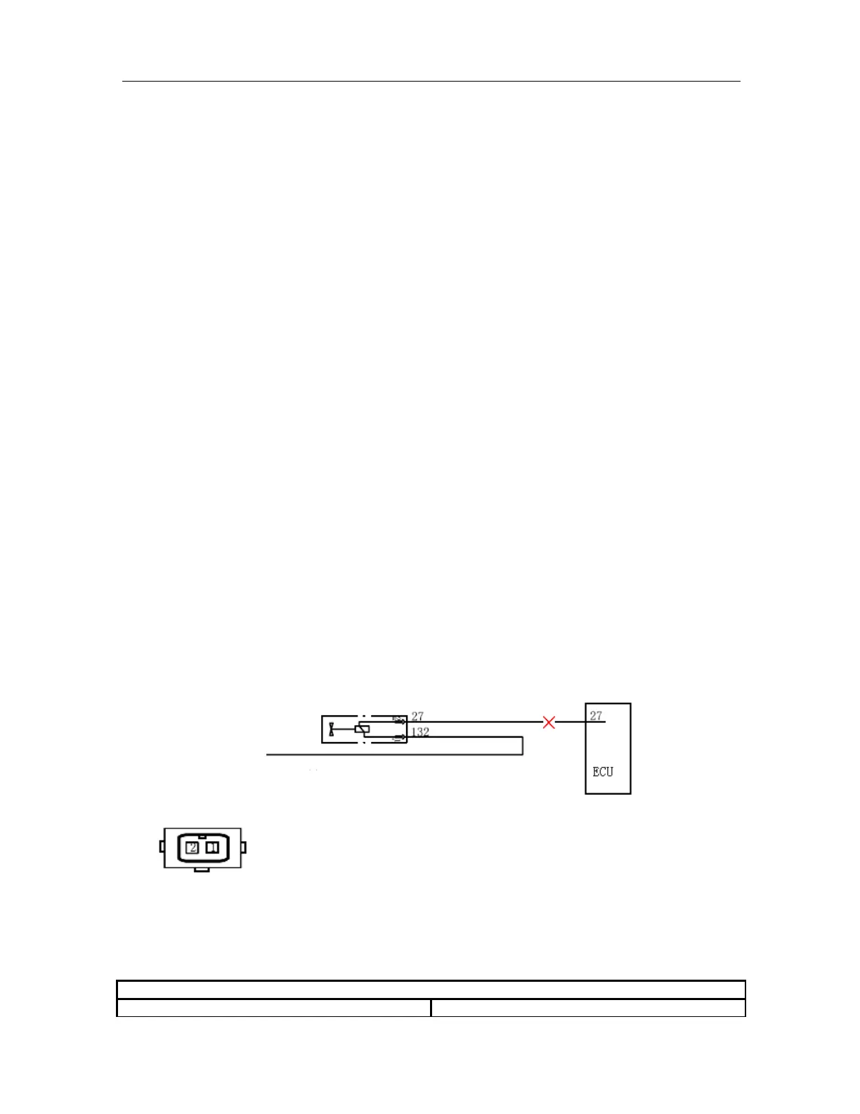
39. P0201 1
st
-Cylinder Fuel Injector Control Circuit Open
Description about Malfunction Cause:
After engine has been started, the circuit voltage is to be measured by the drive module of fuel injector inside
ECU, and when the voltage complies with the voltage in the mode of open circuit, it is determined to be the
malfunction of open circuit.
Schematic Circuit:
Malfunction Diagnostic Guide:
Required Equipment: (Diagnostic Instrument with EOBD Diagnostic Function, Digital Multimeter, and
Correct Circuit Diagram)
Step I: Use diagnostic instrument to read the malfunction information
Main relay