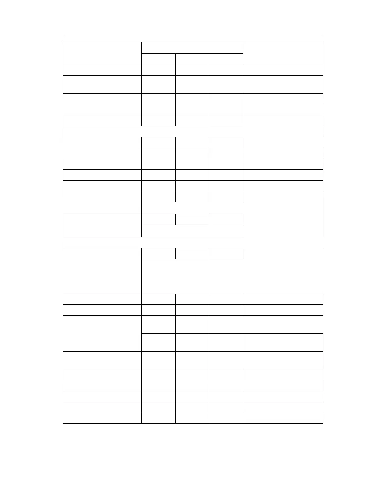
Technique parameters
10
Installation location
Torque rating
Remark
N•m kgf•m ft•lbf
Outlet pipe seat 21.6 2.2 15.8
Thermostat switching
section
21.6 2.2 15.8
thermostat seat 21.6 2.2 15.8
Bypass hose 21.6 2.2 15.8
Bypass tube 21.6 2.2 15.8
Cylinder block and crank connecting rod mechanisms
Crankshaft pulley 162 16.7 118.4
Flywheel 100 10.3 73.1
Clutch partition 8.8 0.9 6.4
Clutch compressing disc 21.6 2.2 15.8
Crankshaft rear cover 8.8 0.9 6.4
Main bearing cap
19.6 2.0 14.3 First determine the
pre-tightening torque, and
then tightening angle.
Please note the use limit of
bolt length (See the
corresponding section)
Tightening 85°~ 95°
Connecting rod cap
24.5 2.5 17.9
Tightening 85°~ 95°
Cylinder head, valve and others
Cylinder head
19.6 2.0 14.3 First determine the
pre-tightening torque, and
then tightening angle.
Please note the use limit of
bolt length (See the
corresponding section)
Tightening 85°~ 95°
Retightening 85°~ 95°
Camshaft cover 12.7 1.3 9.3
Cylinder head cover 8.8 0.9 6.4
Oil pump and timing
sprocket casing
assemblies
21.6 2.2 15.8
Refer to the corresponding
part of figure
45.1 4.6 33.3
Refer to the corresponding
part of figure
Upper guide of timing
sprocket
8.8 0.9 6.4
Timing sprocket guide rail 8.8 0.9 6.4
Tensioner arm 19.1 1.9 14.1
Timing sprocket tensioner 8.8 0.9 6.4
VVT fixing bolt 60 6.12 43.6
Front/rear hooks 45.1 4.6 33.0