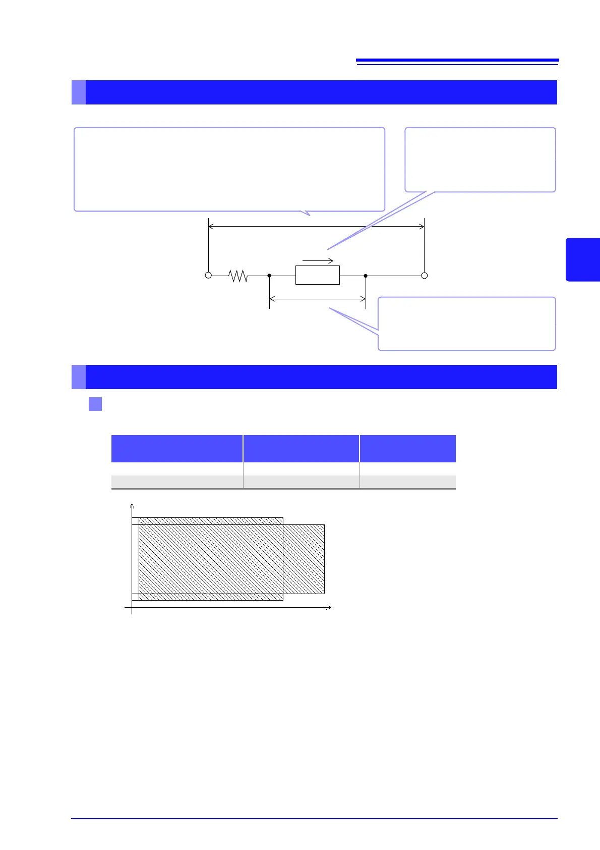
EasyManua.ls Logo

Hioki IM3570 - Page 53

Hioki IM3570
458 pages
To Next Page IconTo Next Page
To Previous Page IconTo Previous Page
Loading...
4.2 Setting Basic Settings of Measurement Conditions
45
4
Chapter 4 LCR Function
Relationship between the measurement signal level of the instrument and the sample is as follows.
When normal mode (p. 54)
About the test signal level
For setting range and accuracy
Output impedance
Object under
test
CC
CV
HL
V
Constant current level (CC)
You should select this if you wish
to set the current passing through
the object to be tested to a con-
stant value.
Constant voltage level (CV)
You should select this if you wish to set the
voltage across the terminals of the object
to be tested to a constant value.
Open circuit voltage level (V)
This voltage value is the value which is applied across the two terminals of
the series combination of the object which is being tested and the output
impedance. As for the voltage which is applied across the terminals of the
object which is being tested (by itself), if required, you should either check
the monitor voltage value, or select constant voltage (CV) and set a voltage
value across these terminals.
Open circuit voltage level (V) and Constant voltage level (CV) setting
Measurement frequency
setting range
Open circuit voltage
setting range
Open circuit voltage
accuracy
4 Hz to 1.000 MHz 0.005 V to 5.000 V ±10%±10 mV
1.0001 MHz to 5.000 MHz 0.010 V to 1.000 V ±20%±10 mV
0.010 V
0.005 V
5.000 V
1.000 V
4 Hz 5 MHz1 MHz

Table of Contents

Other manuals for Hioki IM3570

Related product manuals