4.2 Setting Basic Settings of Measurement Conditions
46
• When Low Z high accuracy mode (p. 54)
Measurement frequency
setting range
Open circuit voltage
setting range
Open circuit voltage
accuracy
4 Hz to 100 kHz 0.005 V to 1 V ±10%±10 mV
4 Hz 5 MHz100 kHz
0.005 V
1.000 V
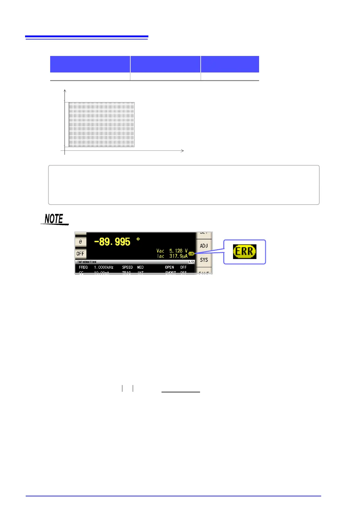
Testing some types of sample is not possible using constant voltage. In this case, the following
symbol appears on the display:
In such a case, constant voltage testing is not performed. Change the constant voltage level
to a value not more than the value being shown as Vmoni.
When a 1 F capacitance is measured at 10 kHz, the CV operation range can be obtained
as follows. Sample impedance
Zm becomes as follows:
Sample impedance
Zm becomes as follows:
The impedance
Zm' observed from the generator is as follows:
Accordingly, the voltage
Vm across both leads of the sample is as follows:
Because the generator output voltage range is 5[mV] to 5[V] for 10 kHz, the CV operation
range per the above expression is
Vm = 0.8[mV] to 0.78[V].
In low Z high accuracy mode, the output resistance
Ro becomes 10[].
• The open circuit voltage that can be set differs depending on the frequency.
• When the test frequency is higher than 1 MHz at an open-circuit voltage of more than 1 V, the
voltage is automatically set to 1 V.
• When the measurement frequency is set higher than 1 MHz at an open circuit voltage of less than 0.010 V,
the voltage is automatically set to 0.010 V.
Xm
1–
2
fC
-----------------=
Zm = Rm + jXm = 0 [
] - j15.9 [
]
Ro: Output resistance (100 [])Zm' = Ro + Zm = 100 [
] - j15.9 [
]
Vm
Zm Vo
Zm
----------------------
15.9
Vo
101.3
--------------------------
==
Vo : generator output
|Zm' |
15.9 [
]×Vo